Portable remote life multi-parameter monitoring terminal and constructed remote monitoring system

A portable, multi-parameter technology, applied in the field of telemedicine, can solve the problems of slow response, no diagnostic function, reliability and stability to be improved, etc., to achieve the effect of reducing workload

Inactive Publication Date: 2011-07-06
RES INST OF XIAN JIAOTONG UNIV & SUZHOU
1 Cites 30 Cited by

AI-Extracted Technical Summary

Problems solved by technology

[0007] The purpose of the present invention is to provide a portable remote life multi-parameter monitoring terminal, which solves the problems in the prior art that the remote medical detection...

Abstract

The invention discloses a portable remote life multi-parameter monitoring terminal and a constructed remote monitoring system. The terminal comprises a microprocessor, a network communication module and a life parameter acquisition module. The terminal is characterized in that: the life parameter acquisition module takes charge of acquiring physiological signals and audio and video information according to the instructions and transmitting the signals to the microprocessor; and after the microprocessor receives, analyzes and processes the physiological signals and the audio and video information of a user, the physiological signals and the audio and video information are transmitted out through the network communication module. The terminal realizes real-time transmission and remote monitoring of multiple physiological parameters of a human body, and can realize brand-new networked and digitalized remote hospital monitoring to meet the requirements of families on remote medicinal treatment, emergency medicinal treatment and the like.

Application Domain

Special data processing applications

Technology Topic

Human bodyInformation transfer +8

Image

  • Portable remote life multi-parameter monitoring terminal and constructed remote monitoring system
  • Portable remote life multi-parameter monitoring terminal and constructed remote monitoring system
  • Portable remote life multi-parameter monitoring terminal and constructed remote monitoring system

Examples

  • Experimental program(1)
  • Effect test(1)

Example Embodiment

[0038] Example
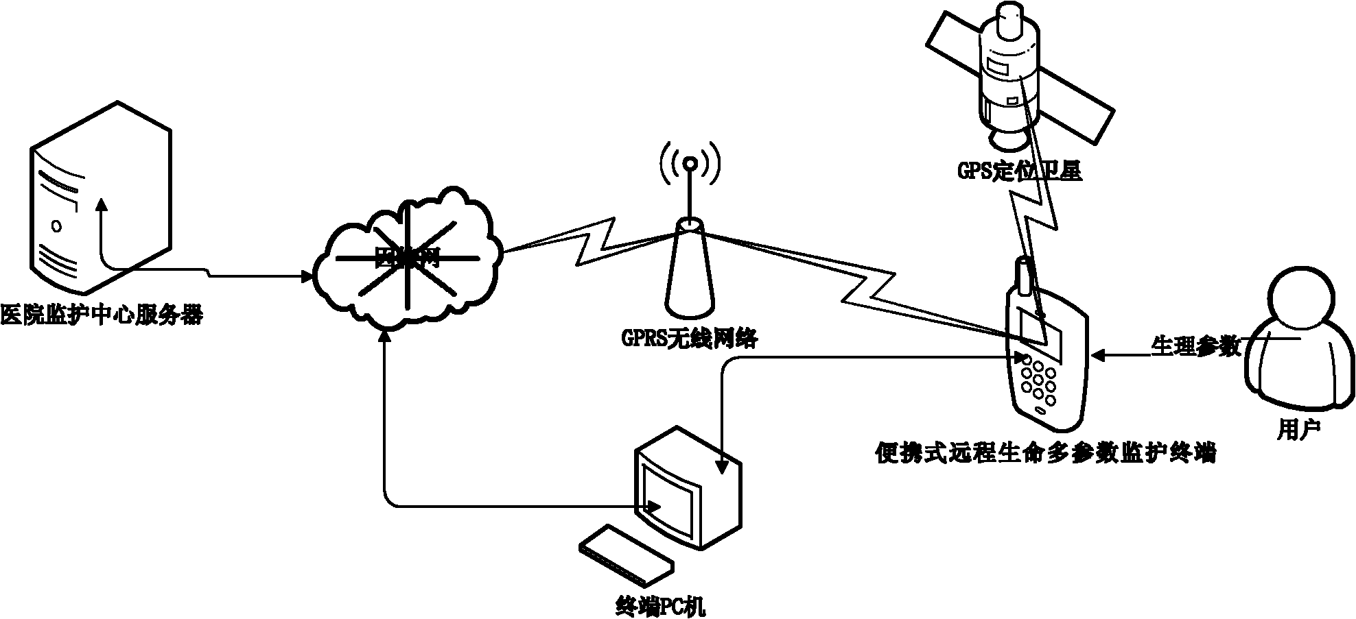
[0039] Such as figure 1 It is a remote monitoring system, including a portable remote life multi-parameter monitoring terminal, a hospital monitoring center server, a terminal PC and a GPS positioning satellite. The hospital monitoring center server is connected to the INTERNET network, and the portable remote life multi-parameter monitoring terminal uses GPRS The network is connected to the INTERNET network, and the data is transmitted through the INTERNET network and the hospital monitoring center server communication. The terminal PC is connected to the INTERNET network to communicate with the hospital monitoring center server to transmit data, and communicates with the portable remote life multi-parameter monitoring terminal via USB. After the portable remote life multi-parameter monitoring terminal communicates with the GPS positioning satellite through the GPS module to locate the geographic location of the portable remote life multi-parameter monitoring terminal, the geographic location information is transmitted to the hospital monitoring center server.
[0040] According to the working principle of the portable remote life multi-parameter monitoring terminal, this monitoring system is wrong! The reference source was not found. Shown. It is mainly composed of a portable remote life multi-parameter monitoring terminal and a hospital monitoring center server. The portable remote life multi-parameter monitoring terminal and the hospital monitoring center server are inseparable from the functional level, but they are relatively independent from the technical development level.
[0041] Such as figure 2 As shown, it is a portable remote life multi-parameter monitoring terminal, including a microprocessor, a network communication module, and a life parameter acquisition module, characterized in that the life parameter acquisition module is responsible for collecting physiological signals and audio and video information according to instructions, and transmitting the signals To the microprocessor; the microprocessor receives the user's physiological signal and audio and video information and then analyzes and processes the physiological signal and audio and video information through the network communication module.
[0042] The life parameter acquisition module includes a physiological signal acquisition module and a video acquisition channel. The physiological signal acquisition module is responsible for collecting human ECG, body temperature, blood pressure, blood sugar and fetal heart sound signals; the video acquisition channel acquisition is in a portable remote life multi-parameter monitoring User audio and video information near the terminal. The network communication module includes a Bluetooth module, a GPRS module, and a GPS module; the Bluetooth module is used to communicate with a computer in the near field to transmit data; the GPRS module communicates with the GPRS network to transmit the collected data to the GPRS network In the remote hospital server; the GPS module is used to realize the location of the geographic location of the portable remote life multi-parameter monitoring terminal.
[0043] The microprocessor is an ARM9+DSP dual-core processor. Each core of the dual-core processor is provided with linear Flash for BIOS, RAM for accelerating system operation and non-linear Flash for storing collected information; the DSP processor is exclusively used For processing audio and video information. The DSP core uses the TMS320C5416 chip; the ARM9 core uses the ARM9 S3C2410 chip; the portable remote life multi-parameter monitoring terminal is also provided with an input/output module, the input module uses a keyboard; the output module uses an LCD display.
[0044] According to the functional requirements of the portable remote life multi-parameter monitoring terminal, the present invention designs a set of hardware system that is convenient for cutting and expanding according to the modular design idea. According to the functional requirements of the biomedical information processing platform of the present invention, the hardware structure is composed of the core part of the system, life parameter sampling and network communication, such as figure 2 It is the main functional module of the hardware platform of the system. The portable remote life multi-parameter monitoring terminal adopts embedded software. The embedded software part is composed of system layer and application layer. The system layer is composed of the operating system layer and the driver layer. It mainly completes the transplantation and expansion of the embedded operating system. The application layer completes the realization of application target programs (such as image 3 Shown)
[0045] The server operating system of the hospital monitoring center is Windows XP, and the system server software system architecture diagram is as follows Figure 4 As shown, the data layer is divided into a database for the purpose of data information storage and management, and a data stream for the purpose of instant message transmission and audio and video communication. The database stores the patient's medical records and physiological data. It also manages the user accounts of the software system and the connection records between the patient and the server. The data stream provides a good end-to-end video, audio, and instant message stream for the server and client, but does not save data.
[0046] The control layer is mainly composed of receiving and sending control, data control and display control. The transceiver control manages a variety of communication schemes, supports mobile terminals to connect via wireless GPRS transmission, and supports community hospital central terminals or home PCs to connect via wired transmission. Data control will directly operate the background database, including data storage, query, modification and deletion control, computer automatic diagnosis control of physiological signals, and user account management control. The display control is mainly responsible for responding to user operations captured by the software interface and feeding back the background data processing results to the software interface.
[0047] The interface layer is the platform for the software system to interact with the user. The physiological signal display interface clearly and accurately depicts the digital ECG I, II, V three-lead waveforms, and other physiological signal index data; the medical record information display interface is concise The display of the basic information of the patient; the audio and video interface supports audio and video communication with the currently connected patient, instant messaging messaging, and the control interface is convenient for users to control the software.
[0048] The following invention describes in detail the implementation process of the portable remote life multi-parameter monitoring terminal.
[0049] 1. Physiological parameter collection
[0050] ECG and body temperature are the basic detection parameters of the monitoring terminal of this system. The ECG detection uses Ag/AgCl electrodes with excellent cost performance. The lead wire adopts a standard five-lead wire (AHA standard: white RA, black LA, brown V, green RL, red LL). Three leads of lead I, lead II and lead V (chest lead) are generated through the Wilson resistance network. As the object of ECG monitoring, if it is used for clinical diagnosis, the more the leads, the more information and the more accurate the judgment. The standard 12-lead is generally used in clinical practice. For monitoring, 3 leads are sufficient. Too many leads will increase the system cost and the communication cost will also increase. The basic parameters of the ECG amplification and acquisition circuit are: +/-2.5mV measurement range, front-end common-mode rejection ratio higher than 80dB, 300Hz sampling rate, 0.05~100Hz bandpass +50Hz power frequency notch filter and at least 100M ohm input Impedance, 10bit AD conversion rate. The body temperature is collected by the ET series high-sensitivity negative temperature coefficient (NTC) thermistor with a resistance of 30K ohms, and the current temperature is obtained through the resistance-temperature meter. The measurement range is 18℃~45℃, and the accuracy is ±0.1℃. Other non-basic parameter measurement modules such as blood pressure, blood glucose, etc. are used as optional modules. The terminal system provides UART serial port to connect with such measurement modules to obtain blood glucose, blood glucose and other parameters. It has been installed in Omron’s upper arm electronic blood pressure monitor HEM-752 ( Error ± 4mmHg), Johnson & Johnson Steady Step Glucometer OneTouch SureStep Glucometer (measurement range 0 ~ 33.3mmol/L, error 0.1mmol/L) and the fetal heart sound collector developed by our laboratory (using ultrasound Doppler and DSP technology , The test is successful on the measuring range 60~240bpm.
[0051] 2. ECG data storage and calculation
[0052] Each ECG data sampled by the MCU built-in AD converter is 10bit, which is not compatible with the current byte alignment of the memory. The storage of ECG data must consider both efficiency and compression rate. Table 2 shows the comparison of the three storage methods (assuming the sampling rate is 300Hz). The fastest data access speed can be achieved by adopting byte-aligned mode; while the compact mode can achieve the highest memory utilization. Another solution is a compromise between the above two solutions, but it can directly support 12bit AD converters. If the data is stored in an SD (or microSD) card, when a compromise solution is adopted, a 2GB storage card can store ECG data for up to half a month of continuous monitoring.
[0053] Table 1 Three kinds of ECG storage methods and their comparison
[0054]
[0055] The next step is to calculate the relevant parameters based on the collected data, such as instantaneous and average heart rate, PR interval, QT interval, etc. This article uses threshold and slope-based methods to detect QRS waves. According to the calculated parameter value and the normal range, it is judged whether the physiological state of the user is normal or not, so as to realize the self-diagnosis function. In order to meet the real-time requirements of the system, taking into account the computing power of the terminal, the sampled ECG data does not undergo complex digital processing. The system provides users with static and dynamic display solutions. The static display allows the user to observe the physiological data information in a specific time period, while the dynamic display always displays the current latest sampling information.
[0056] 3. GPS positioning
[0057] The user's location information is obtained by reading the output information of the GPS module through UART, and the user's longitude and latitude coordinates are obtained by picking up the GPRMC or GPGGA sentences output by the GPS. The display of GPS positioning information on the terminal uses a method similar to the positioning software OziExplorer. The basic idea is to know the precise longitude and latitude coordinates of any non-overlapping 3 points (preferably scattered) on a map (geographical picture for positioning) as The calculated basic points can be used to calculate the latitude and longitude of any point on the map based on these three coordinates; conversely, the corresponding point can also be displayed on the map based on the latitude and longitude. GPS positioning test shows that the positioning error of the terminal GPS system is within a range of tens of meters (including GPS module error and map error), which is completely sufficient for medical staff to find the current location of the user in emergency situations.
[0058] 4. Data upload
[0059] The monitoring terminal can send data to the hospital monitoring center server through a variety of communication methods. This system comprehensively considers the cost and convenience to transmit data in two ways: one is to connect the terminal device to the PC, and the PC displays each At the same time, the data is transmitted to the server of the hospital monitoring center. This method requires almost no communication cost; the other is to enter the Internet wirelessly through the GPRS module on the terminal, and transmit the data to the monitoring center. Receives the UART from the MPU, uses the standard AT command set to control the data reception and transmission of the GPRS module. The GPRS module can automatically identify the baud rate. The current baud rate is 19200. In order to ensure the reliable transmission of physiological parameters, a standard CRC check is also used to verify the integrity and correctness of the data. The content of the transmitted data includes user ID, data type flag, time, data length, data itself and check code.
[0060] 5. Embedded operating system
[0061] In order to improve the real-time performance and stability of the system, this paper adopts real-time operating system (RTOS) μC/OS-II for task management. According to interrupt correlation, urgency and criticality, all operations are divided into task priority. The priority order is data reception, data collection, data transmission, keyboard and touch screen input, data processing, and finally display tasks. At the same time, in order to facilitate the management of large-capacity storage devices, the μC/FS file system is transplanted to directly support the FAT file system on Windows. Use μC/GUI to design the human-computer interaction interface of the terminal system to achieve a good human-computer interaction effect under the premise of occupying less resources.
[0062] The following is a detailed description of the implementation process of the hospital monitoring center server:
[0063] 1. Server software design
[0064] The server database design structure of the hospital care center is as follows Image 6 Shown. The database adopts VC+++MS SQL Server 2000 development environment, and the database programming adopts MS ODBC specification and its standard API for database access. The back-end database maintains five entries and maintains a data source mapping—record set in the program. The program indirectly operates the database by operating the record set to realize user requests such as searching, adding, editing, and deleting.
[0065] This article uses the rich communication features provided by the operating system and the instant messaging COM component RTC provided by Microsoft to implement audio and video calls, instant messaging, application and drawing board sharing and other functions. Using the API provided by RTC enables the software system to create calls between PC-PC, PC-phone, and phone-phone via the Internet. RTC selects audio decoders according to the capabilities and bandwidth of both parties, and can support a variety of decoders including G.711, G.722.1, G.723, GSM, DVI4 and SIREN. There are two types of video decoders: H.263 and H.261. The first choice in this article is H.263, with a bit rate of 6Hbps~125Kbps, and supports two media formats, OCIF and CIF. The video capture mode is MSH263.
[0066] 2. Communication protocol and interface design
[0067] Server software systems usually need to process data connection tasks of multiple clients at the same time. In order to process connection requests in a timely and accurate manner, the design uses multithreading technology to achieve concurrency control. Figure 7 shows the detailed design framework of the communication interface of the monitoring center software. The main thread is responsible for maintaining the monitoring thread. The thread monitors whether there is user data coming, and generates a new communication thread. The communication thread establishes a data communication channel with the user for reliable data transmission, and the monitoring thread continues to monitor whether the port is available Data requests from other users.
[0068] In order to enable the server to transmit data with the client, the present invention designs and develops a set of reasonable and complete communication protocols. The communication protocol can be divided into the following parts: 1) Handshake signal. The user ID is encapsulated in the packet. Used by the client to request a connection from the server. 2) The server receives the handshake signal, parses the data packet, and establishes a connection channel with the user after confirming the ID. 3) The client receives the confirmation message from the server and starts to send physiological data packets. The ECG data with a large amount of data can be divided into multiple data packets and sent sequentially. Different types of data packets are distinguished by different identifiers, and information such as packet sequence and sending time are encapsulated in the packets. The server receives the data packet, parses its content, performs a CRC check, and according to whether the check result is correct, notifies the client to continue sending the next packet or resending the current data. 4) After the data is sent, the client sends an end signal to the server. The server confirms the physiological data type, and feeds back the automatic diagnosis result of the computer to the client, or directly informs the client to close the channel and end the communication.

PUM

no PUM

Description & Claims & Application Information

We can also present the details of the Description, Claims and Application information to help users get a comprehensive understanding of the technical details of the patent, such as background art, summary of invention, brief description of drawings, description of embodiments, and other original content. On the other hand, users can also determine the specific scope of protection of the technology through the list of claims; as well as understand the changes in the life cycle of the technology with the presentation of the patent timeline. Login to view more.

Similar technology patents

Installing method of portal crane

InactiveCN1833988ACable Wind Adjustment Reductionreduce workload
Owner:TONGJI UNIV

Automatic report generating method capable of meeting power distribution network management specific data standards

InactiveCN103714492Areduce workloadVersatile and practical
Owner:GUANGXI POWER GRID ELECTRIC POWER RES INST +1

Classification and recommendation of technical efficacy words

  • reduce workload

Hospital gown

InactiveUS7181773B1reduce workloadquickly expose
Owner:WILLIAM BEAUMONT HOSPITAL

Performance Aware Peer-to-Peer Content-on-Demand

ActiveUS20090177792A1reduce workloadimproves perceive performance
Owner:THOMSON LICENSING SA

Method and apparatus for directionally grabbing page resource

InactiveCN101452463AIncrease yield and recallreduce workload
Owner:ZHEJIANG UNIV

Garbage classification prompt garbage can and system based on image recognition

InactiveCN107054936Areduce workloadachieve reuse
Owner:GUANGDONG MATVIEW INTELLIGENT SCI & TECH CO LTD

Construction site operation safety remote management and control system and method

InactiveCN107967562AReduce workloadSave human and material resources
Owner:TAIYUAN POWER SUPPLY COMPANY OF STATE GRID SHANXI ELECTRIC POWER +1
Why Eureka
Try Eureka