System and method for cooling motor with liquid

A liquid cooling and liquid technology, applied in the direction of electrical components, electromechanical devices, electric components, etc., can solve the problems of easy failure, heat removal, inability to fully cool or even lubricate the bearing, and achieve the effect of prolonging the service life

Inactive Publication Date: 2011-07-06
TIANJIN SANTROLL ELECTRIC AUTOMOBILE TECH CO LTD
View PDF0 Cites 6 Cited by
  • Summary
  • Abstract
  • Description
  • Claims
  • Application Information

AI Technical Summary

Problems solved by technology

[0004] 1. The end of the motor stator winding is generally located in the air cavity on both sides of the stator. The temperature is very high, and it is difficult to get good liquid cooling, so it is prone to failure, especially the winding on the upper side of the motor circumference, which often burns out. Bad
[0005] 2. Some liquid cooling methods do not pass near the bearing, so the bearing cannot be fully cooled or even lubricated
The bearing rotates at high speed for a long time, the failure rate is high, and the service life is short
[0006] 3. When heat is generated near the bearing, it is easy to cause poor fit between the bearing chamber, bearing and shaft, and then cause wear of the bearing chamber and shaft, making it difficult to repair
[0007] 4. Even if some liquid cooling methods can focus on these parts, it is difficult to take away the heat in the middle part composed of the stator and the shaft.
[0008] At present, there is no motor in the market that can not only dissipate heat well for the windings, but also take away more heat from the middle of the stator and rotor, lubricate the bearings, fully cool the bearings, bearing chambers, and shafts, and have greater adaptability. liquid cooling device

Method used


Image

  • System and method for cooling motor with liquid
  • System and method for cooling motor with liquid

Examples


Embodiment Construction

[0023] Below in conjunction with accompanying drawing, the specific embodiment of the invention is described in further detail:

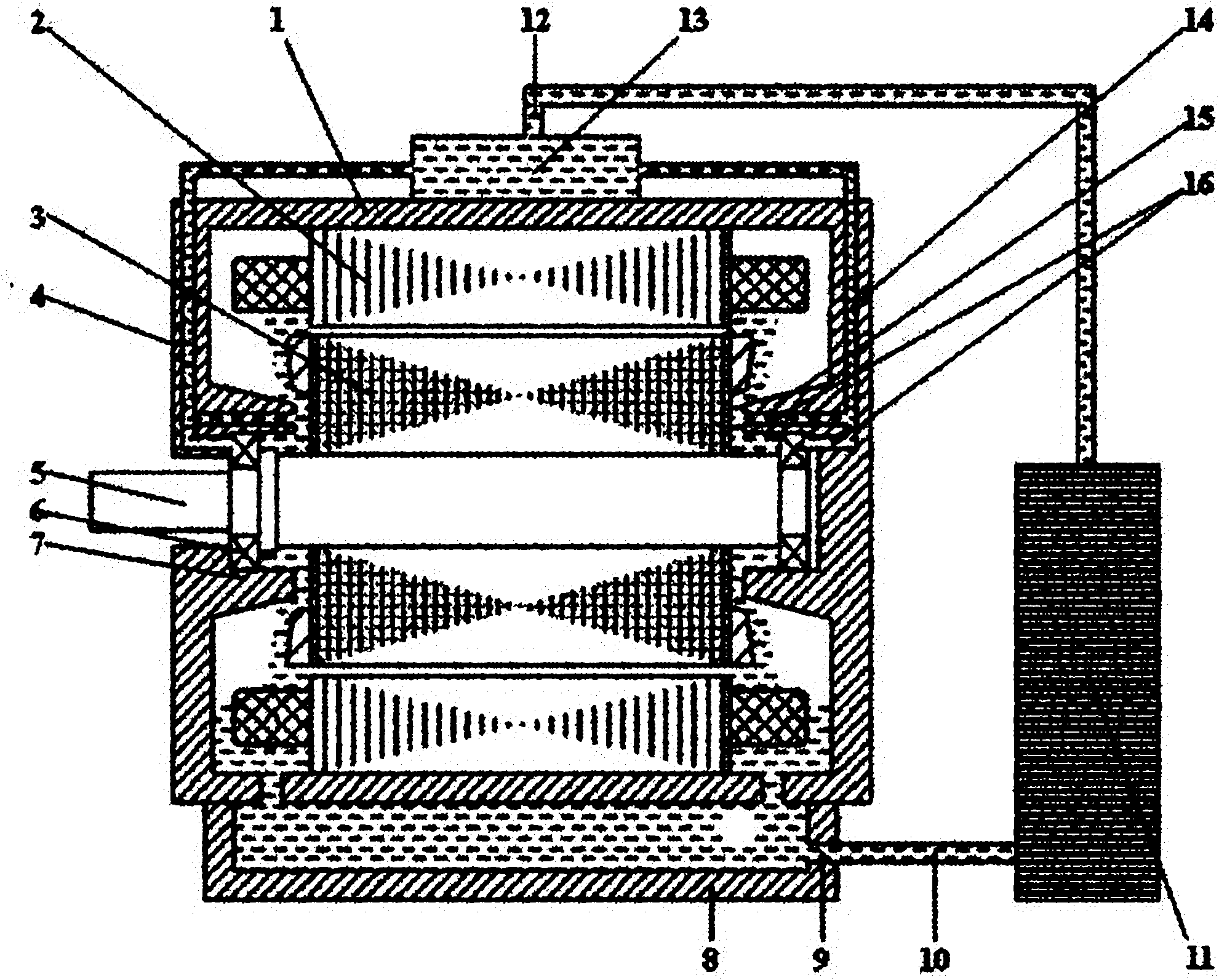
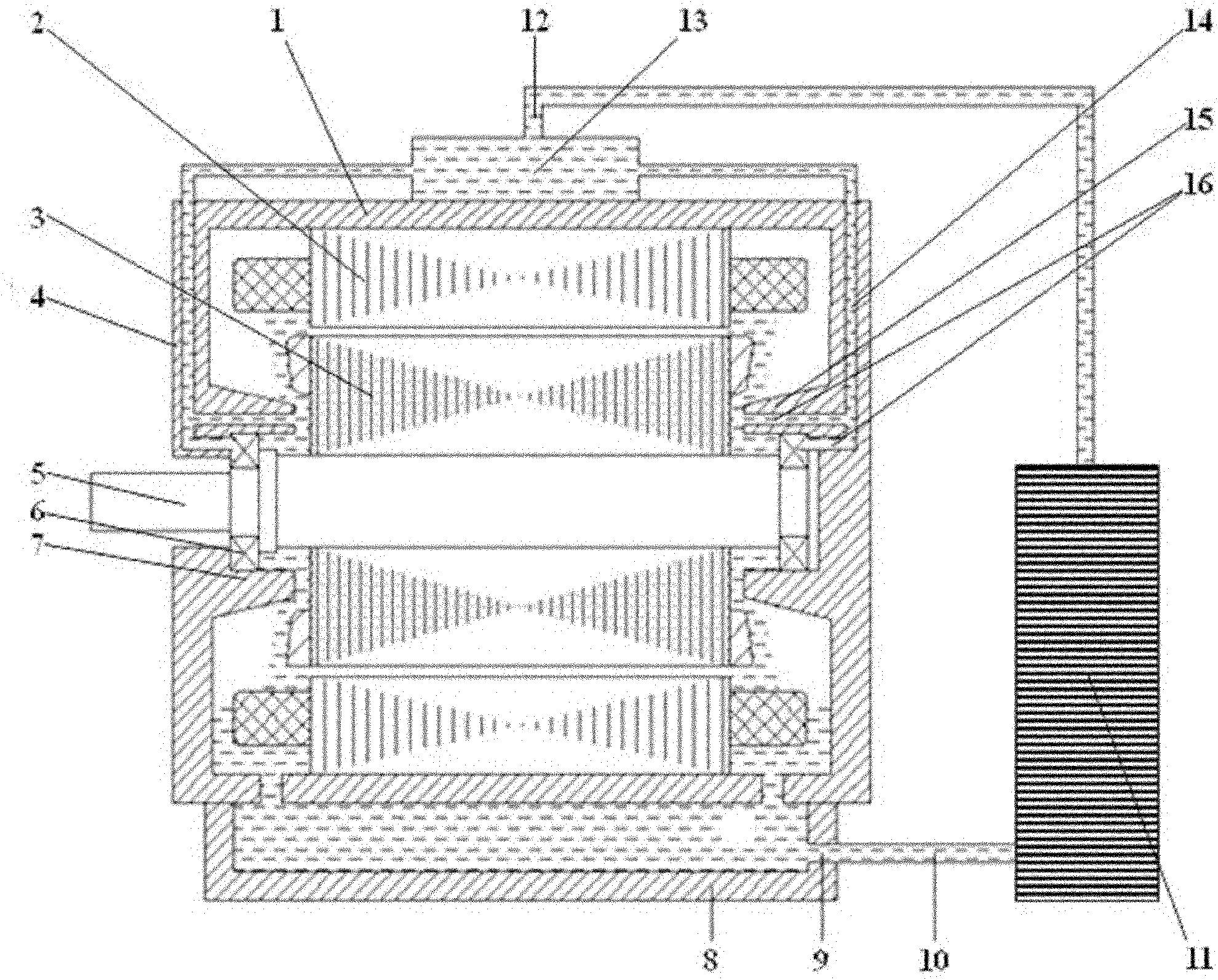
[0024] figure 1 , is a typical specific implementation, and the housing 1, stator 2, rotor 3, end cover 4, shaft 5, bearing 6, and bearing chamber 7 basically constitute a motor system.

[0025] The liquid storage tank 8, the liquid outlet 9, the liquid pipeline 10, the liquid external circulation device 11, the liquid inlet 12, and the liquid distribution box 13 basically constitute a liquid external circulation system.

[0026] The wall of the bearing chamber 7 is provided with an injection port 16, and the liquid ejected from the injection port 16 flows through the vicinity of the bearing 5 or its balls, and after cooling the bearing 6, it jets to the shaft 5 superior.

[0027] A protrusion 15 is also provided, and the protrusion 15 is connected to the inner end surface of the side wall of the bearing chamber 7 .

[0028] The injection port 16...


PUM


Abstract

The invention discloses a system and a method for cooling motor with liquid, relates to the field of motor cooling and aims to realize the liquid-cooling heat dissipation of all parts in the motor. The system comprise a casing (1), a stator (2), a rotor (3), an end cover (4), a shaft (5), a bearing (6), a bearing chamber (7), a liquid storage groove (8), a liquid outlet (9), a liquid pipeline (10), a liquid external circulation device (11) and a liquid inlet (12), and further comprises a liquid distribution box (13), a jet pipeline (14), a projection (15) and a jet orifice (16). Liquid jets out from the periphery of the bearing (6) through the jet orifice (16) and cools the bearing (6), and then jets to the rotor (3) and forms a vortex under the combined rotation action of the rotor (3), the shaft (5) and the bearing (6), thereby adequately achieving a cooling function. Therefore, the liquid can be sprayed onto other parts in an internal cavity of the motor. The system and the method, provided by the invention, are mainly applied to rotary structures such as the motor comprising the bearing, the shaft and the like.

Description

technical field [0001] The invention relates to the field of motor cooling, in particular to a motor liquid cooling system and method. Background technique [0002] Existing motor cooling designs generally adopt three methods: natural air cooling, forced air cooling, and liquid cooling. Among them, the liquid cooling method is suitable for efficient heat dissipation inside high-power motors and has been widely used. [0003] However, the existing motor liquid cooling method still has the following defects: [0004] 1. The end of the motor stator winding is generally located in the air cavity on both sides of the stator. The temperature is very high, and it is difficult to get good liquid cooling, so it is prone to failure, especially the winding on the upper side of the motor circumference, which often burns out. Bad. [0005] 2. Some liquid cooling methods do not pass near the bearing, so the bearing cannot be fully cooled or even lubricated. The bearing rotates at high ...

Claims


Application Information

Patent Timeline
Patent Type & Authority Applications(China)
IPC IPC(8): H02K9/19H02K9/197
Inventor 刘延海高栓邦张福增
Owner TIANJIN SANTROLL ELECTRIC AUTOMOBILE TECH CO LTD
Why Eureka
Try Eureka