[0023] Refer to the following Figure 1 to Figure 6 , And further describe the preferred embodiments of the present invention in detail. The multiple embodiments of the present invention can have multiple variations, and the scope of the present invention is not limited by the multiple embodiments described below, and is only used to provide those of ordinary skill in the art to which the multiple embodiments of the present invention belong. More detailed description. Therefore, in order to more clearly emphasize and explain the problem, the shapes of the various components shown in the drawings may be exaggerated.
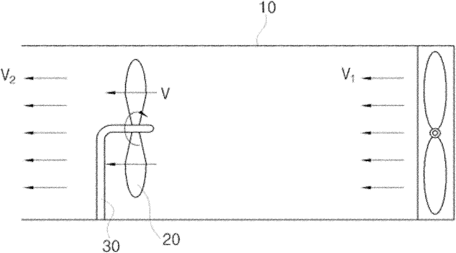
[0024] figure 1 Shown is a situation where the propeller is set in a wind tunnel. The wind tunnel 10 is arranged horizontally, a fan is arranged at the right end of the wind tunnel, and an exhaust port is formed at the left end of the wind tunnel. The fluid flow (V1) provided by the fan passes through the (V) propeller 20 and then faces the (V2) exhaust port.
[0025] The propeller 20 is rotatably provided on the support member 30. The propeller 20 is arranged substantially perpendicular to the wind tunnel 10, and the propeller 20 is rotated by the fluid flow (V) inside the wind tunnel 10.
[0026] figure 2 Shown is a propeller according to an embodiment of the invention, image 3 and Figure 4 Shown as figure 2 A sectional view of the propeller blade shown.
[0027] The propeller 20 includes first and second rotating blades 22 and 26. figure 2 (a) shows a conventional propeller 20, figure 2 (b) shows the propeller 20 in an embodiment of the invention. Unlike the conventional propeller 20, the first and second rotating blades 22, 26 have a plurality of flow paths 24, 28, respectively. Such as figure 2 As shown in (b), the plurality of flow paths 24, 28 are arranged substantially perpendicular to the length direction of the rotating blades 22, 26, and are arranged parallel to each other. The plurality of flow paths 24 and 28 are arranged separated from the ends of the rotating blades 22 and 26 to the center of rotation of the rotating blades 22 and 26.
[0028] At this time, such as image 3 As shown, the flow path 24 has an inlet 24i and an outlet 24o. The inflow port 24i is positioned forward with respect to the rotation direction, and the outflow port 24o is positioned backward with respect to the rotation direction. That is, with figure 2 (b) As a reference, the propeller 20 rotates in the counterclockwise direction, the inflow port 24i is formed in the lower part of the flow path 24, and the outflow port 24o is formed in the upper part of the flow path 24.
[0029] In addition, such as image 3 and Figure 4 As shown, the width (di) of the inflow port 24i is wider than the width of the outflow port 24o. That is, the cross-sectional area of the inflow port 24i is larger than the cross-sectional area of the outflow port 24o. In addition, the cross-sectional area of the inflow port 24i gradually decreases toward the outflow port 24o.
[0030] On the other hand, the flow path 28 formed in the second rotating blade 26 and the flow path 24 formed in the first rotating blade 22 are in a 180° rotational symmetry relationship. That is, if the first rotating blade 22 is rotated by 180° with the rotation center as a reference, it has the same structure as the second rotating blade 26.
[0031] As observed above, there is a fluid flow (V) caused by a fan in the wind tunnel 10, and the fluid flow (V) impacts the propeller 20 and causes the propeller 20 to rotate. At this time, the fluid flow (V) flows into the flow path 24 through the inflow port 24i, flows along the flow path 24, and leaves the flow path 24 through the outflow port 24o. At this time, the cross-sectional area of the inlet 24i gradually decreases, so the velocity (Vo) of the fluid flow (V) measured at the outlet 24o is greater than the velocity (V) of the fluid (V) measured at the inlet 24i . That is, it can be seen that the fluid flow (V) accelerates from the inflow port 24i to the outflow port 24o.
[0032] Figure 5 and Image 6 Shown as using figure 2 A graph of the experimental results obtained with the propeller shown. First, the experimental conditions will be described. The rotation speed of the fan installed in the wind tunnel 10 is set to 1800 rpm, and the rotation speed is kept constant during the test. In addition, the distance between the propeller 20 and the fan installed in the wind tunnel 10 is approximately maintained at 400 mm.
[0033] First of all, Figure 5 Shown is a calculation diagram of the change in the number of revolutions of the propeller 20 based on the number of the plurality of flow paths 24 and 28 formed in the rotating blades 22 and 26. Such as figure 2 As shown in (b), a plurality of flow paths 24, 28 are sequentially formed by the ends of the rotating blades 22, 26 up to the center of rotation of the rotating blades 22, 26. For example, when five flow paths 24, 28 are formed, The multiple flow paths 24, 28 from No. 1 to No. 5, but the multiple flow paths 24, 28 from No. 6 to No. 9 are not formed.
[0034] Observed Figure 5 Compared with the case where multiple flow paths 24 and 28 are not formed (N=0), when multiple flow paths 24 and 28 are formed (N=1, 2, ..., 9), the number of revolutions is expressed as In particular, when the flow paths 24 and 28 are formed in multiple numbers (N=2, 3, .., 9), the number of revolutions appears to increase sharply. Figure 5 ■ in represents the average value of the measured revolutions.
[0035] That is, in the case of forming a plurality of flow paths 24, 28 with a cross-sectional area of the inlet 24i larger than the cross-sectional area of the outlet 24o, it can be seen that the rotation efficiency of the propeller 20 increases. This is expected to be due to the plurality of flow paths 24, 28 The velocity of the upper fluid flow (V) increases, so an additional vector force is generated, which increases the rotational force.
[0036] Image 6 Shown is a calculation diagram of the change in the rotational efficiency of the propeller 20 based on the number of the plurality of flow paths 24 and 28 formed in the rotating blades 22 and 26. Similarly, as figure 2 As shown in (b), a plurality of flow paths 24, 28 are sequentially formed by the ends of the rotating blades 22, 26 up to the center of rotation of the rotating blades 22, 26. For example, in the case of forming five flow paths 24, 28, A plurality of flow paths 24, 28 from No. 1 to No. 5 are formed, but a plurality of flow paths 24, 28 from No. 6 to No. 9 are not formed.
[0037] Observed Image 6 Compared with the case where multiple flow paths 24 and 28 are not formed (N=0), when multiple flow paths 24 and 28 are formed (N=1, 2, ..., 9), the number of revolutions is expressed as Increased, especially when the flow paths 24, 28 are formed with multiple (N=2, 3, .., 9), the rotation efficiency is shown to be 5 times the rotation efficiency when one flow path 24, 28 is formed -8 times.
[0038] According to the above description, the propeller 20 can have high energy conversion efficiency. That is, a constant fluid flow (V) is accelerated on the flow path 24, so that the rotating blades 22, 26 have a higher rotation speed. Therefore, it can be seen that the constant energy can be converted into higher mechanical energy, and it can be seen that it has high energy conversion efficiency. .
[0039] Although the present invention is described in detail through preferred embodiments, there may be a plurality of embodiments with different forms. Therefore, the scope of technical ideas in the multiple claims recorded below is not limited to the preferred embodiments. On the other hand, the fluid described in this embodiment includes gas and liquid.
[0040] On the other hand, although in this embodiment, the plurality of flow paths 24 and 28 are described centering on the cross-sectional area sizes of the inlet 24i and the outlet 24o, in order to prevent the fluid flow (V) from flowing into the flow path 24, In 28, entrance and exit loss (entrance and exit loss) (loss due to the peeling of the fluid, or loss of head) occurs, the shape and width of the inlet 24i and the outlet 24o (di, do) Can be different. In particular, by deforming the shape of the inflow port 24i and the outflow port 24o into a streamlined shape, the drag force generated by the fluid flow (V) can be minimized, and especially as the velocity of the fluid flow (V) increases, The width (di, do) of the inlet 24i and the outlet 24o can be adjusted. The contents described above are all applicable to the propeller 20 described previously, the propeller 20 described below, and the wing 40 described below.
[0041] Embodiment of the invention
[0042] Figure 7 Shown is a propeller according to another embodiment of the present invention. versus figure 2 (b) Differently shown in (b), the flow paths 24 and 28 can be arc-shaped with the rotation center of the propeller 20 as a reference.
[0043] According to the above description, it can be seen that the rotation efficiency is improved due to the multiple flow paths 24, 28, especially the fluid flows from the wide inflow port 24i to the narrower outflow port 24o, and the velocity of the fluid flow (V) increases. , The rotation efficiency is also improved.
[0044] Figure 8 Shown is a wing 40 according to yet another embodiment of the invention. Such as Figure 8 As shown, the wing 40 has a front end 42 located on the upstream side with respect to the fluid flow (V), and a rear end 44 located on the downstream side with respect to the fluid flow (V). The fluid flow (V) flows through the front end 42 of the wing 40 along the top 46 and the bottom of the wing 40 and leaves the wing 40 through the rear end 44 of the wing 40.
[0045] The wing 40 has a flow path 48 formed by a recessed top 46, and the flow path 48 has an inlet 48i and an outlet 48o. The inflow port 48i is located at the front end 42 of the wing 40, and the outflow port 48o is located at the rear end 44 of the wing 40.
[0046] In addition, such as Figure 8 As shown, the width of the inflow port 48i is wider than the width of the outflow port 48o. That is, the cross-sectional area of the inflow port 48i is larger than the cross-sectional area of the outflow port 48o. In addition, the cross-sectional area of the inflow port 48i gradually decreases toward the outflow port 48o.
[0047] As observed above, the fluid flow (V) flowing along the top 46 of the wing 40 flows into the flow path 48 through the inlet 48i, flows along the flow path 48, and leaves the flow path 48 through the outlet 48o. At this time, the cross-sectional area of the inflow port 48i gradually decreases, so the velocity of the fluid flow (V) measured at the outflow port 48o is greater than the velocity of the fluid flow (V) measured at the inflow port 48i. That is, it can be seen that the fluid flow (V) accelerates from the inflow port 48i to the outflow port 48o.
[0048] Therefore, the difference between the velocity of the fluid flow (V) flowing along the top 46 of the wing 40 and the velocity of the fluid flow (V) flowing along the bottom of the wing 40 increases, thereby making the top 46 of the wing 40 and the aircraft The pressure difference between the bottoms of the wings 40 also increases. This increases the lift force (L) acting on the wing (V).
[0049] With the help of the flow path 48, the velocity of the fluid flow (V) flowing along the top of the wing 40 increases. According to Bernoulli's equation, the velocity and pressure are inversely proportional, so the top 46 of the wing 40 is The pressure difference between the bottoms of the wings 40 increases, and the lift force (L) acting on the wings (V) increases. Therefore, it can be seen that the magnitude of the lifting force of the same fluid flow (V) can be increased by the flow path 48, and the energy conversion efficiency can be improved by the flow path 48.
[0050] Industrial application
[0051] The invention can be used in various products using blades and wings.