Ultrasonic diagnosis apparatus, medical image processing apparatus, and medical image diagnosis apparatus

A diagnostic device, medical image technology, applied in the directions of sonic diagnosis, ultrasonic/sonic/infrasonic diagnosis, infrasound diagnosis, etc., can solve the problem of lack of popularization and other problems

Active Publication Date: 2013-04-10
TOSHIBA MEDICAL SYST CORP
View PDF4 Cites 0 Cited by
  • Summary
  • Abstract
  • Description
  • Claims
  • Application Information

AI Technical Summary

Problems solved by technology

However, this requires special equipment and is not widely used in the field of medical image diagnosis equipment

Method used


Image

  • Ultrasonic diagnosis apparatus, medical image processing apparatus, and medical image diagnosis apparatus
  • Ultrasonic diagnosis apparatus, medical image processing apparatus, and medical image diagnosis apparatus
  • Ultrasonic diagnosis apparatus, medical image processing apparatus, and medical image diagnosis apparatus

Examples


no. 1 approach

[0041] Hereinafter, the first embodiment will be described with reference to the drawings.

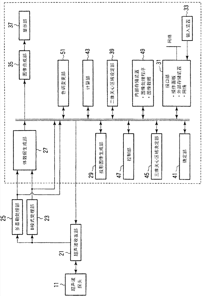
[0042] figure 1 A block diagram of the ultrasonic diagnostic apparatus of this embodiment is shown. As shown in the figure, the present ultrasound diagnostic apparatus includes an ultrasound probe 11, an ultrasound transmission / reception unit 21, a B-mode processing unit 23, a Doppler processing unit 25, a volume data generation unit 27, a projection image generation unit 29, an interface unit 31, Input device 33, image synthesis unit 35, display unit 37, two-dimensional region of interest setting unit 39, determination unit 41, calculation unit 43, three-dimensional region of interest determination unit 45, control unit 47, internal storage device 49, color tone change unit 51 . In addition, the ultrasound diagnostic apparatus may be connected to a biological signal measurement unit (not shown) represented by an electrocardiograph, a cardiograph, a pulse recorder, and a respiration sens...

no. 2 approach

[0079] Hereinafter, the second embodiment will be described with reference to the drawings.

[0080] The difference from the first embodiment is that it is not based on the average contribution value. Instead, the sum of the voxel values ​​of the voxels contained in the set three-dimensional area becomes the largest from the projection surface of the VR image. The 3D-ROI is determined by the distance in the direction of the line of sight.

[0081] Figure 7 A block diagram of the ultrasonic diagnostic apparatus of this embodiment is shown.

[0082] Hereinafter, among the constituent elements of the second embodiment and the first embodiment, constituent elements that perform different operations and the three-dimensional region setting unit 42 will be described. In addition, in the case of implementing the technical idea of ​​the ultrasonic diagnostic apparatus with a medical image processing apparatus, for example, Figure 7 The structure within the dashed line.

[0083] The three-d...

no. 3 approach

[0094] Hereinafter, a third embodiment will be described with reference to the drawings.

[0095] The difference from the first and second embodiments is that the sum of the voxel values ​​of the voxels contained in the set three-dimensional area includes the voxel values ​​of the voxels contained in the shell of the three-dimensional area The difference of the sum becomes the largest, and the distance along the line of sight from the projection surface of the VR image determines the 3D-ROI.

[0096] The module structure diagram of this embodiment and the module structure diagram of the second embodiment Figure 7 the same. Hereinafter, among the constituent elements of the second embodiment and the first embodiment, constituent elements that perform different operations and the three-dimensional region setting unit 42 will be described. In addition, in the case of using a medical image processing device to realize the technical idea of ​​the ultrasonic diagnostic device, for exam...


PUM


Abstract

According to one embodiment, an ultrasonic diagnosis apparatus includes an ultrasonic probe, an ultrasonic transmission / reception unit, a volume data generating unit, a projected image generating unit, a two dimensional region-of-interest setting unit, a specifying unit, a calculation unit and a three-dimensional region-of-interest determination unit. The specifying unit specifies cells on rays which pass through the respective pixels in the 2D-ROI and are used to acquire a VR image. The calculation unit calculates the contribution degree of each cell based on the voxel value and opacity of each cell specified and calculates the average value of the contribution degrees of cells equal in distance from the screen of the VR image along the line-of-sight direction. The three-dimensional region-of-interest determination unit specifies the distances from the screen of the VR image which correspond to average contribution values exceeding the predetermined threshold and determines the position of the 3D-ROI in the volume data.

Description

[0001] The present invention is based on a Japanese invention patent application with an application date of January 8, 2010 and an application number of 2010-003301. The priority of the prior patent application is claimed, and all the technical content of the prior patent application is included in this Inventing. Technical field [0002] The invention relates to an ultrasonic diagnostic device, a medical image processing device and a medical image diagnosis device. Background technique [0003] In various image diagnosis apparatuses in recent years, it is possible to obtain not only a two-dimensional image of one cross-section, but also three-dimensional image data (hereinafter referred to as volume data). In order to analyze the obtained volume data, various display methods that are easy for users to understand are proposed. [0004] As a method of displaying volume data, for example, a method of displaying three arbitrary cross-sections (hereinafter referred to as MPR (Multipla...

Claims


Application Information

Patent Timeline
Patent Type & Authority Patents(China)
IPC IPC(8): A61B8/00G06T17/00
CPCG06T19/00A61B8/14G01S7/52063A61B8/461G01S15/8993A61B8/483G06T2210/41G06T15/08
Inventor 金山侑子神山直久冈村阳子
Owner TOSHIBA MEDICAL SYST CORP
Why Eureka
Try Eureka