Integral brake control mechanism for operating bed

A brake control, operating bed technology, applied in the field of parking brakes, to achieve the effect of eliminating damage

Inactive Publication Date: 2011-07-13
MAQUET SUZHOU
View PDF5 Cites 4 Cited by
  • Summary
  • Abstract
  • Description
  • Claims
  • Application Information

AI Technical Summary

Problems solved by technology

If the movement occurs during the operation, it will lead to unforeseen catastrophic consequences and cause serious medical accidents

Method used


Image

  • Integral brake control mechanism for operating bed
  • Integral brake control mechanism for operating bed
  • Integral brake control mechanism for operating bed

Examples


Embodiment Construction

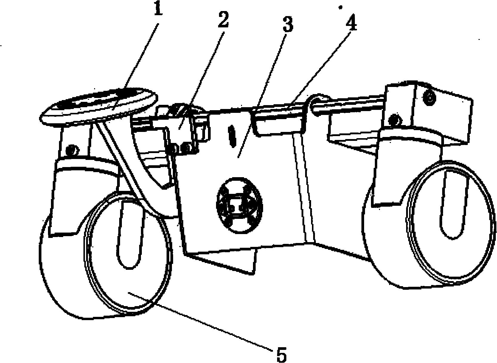
[0013] Such as figure 1 The overall braking control mechanism for an operating bed includes a bracket 3, a universal wheel 5 is installed on both sides of the bracket 3, a connecting rod 4 is arranged between the two universal wheels 5, and a connecting rod 4 is installed on the connecting rod 4. There is pedal assembly 1.

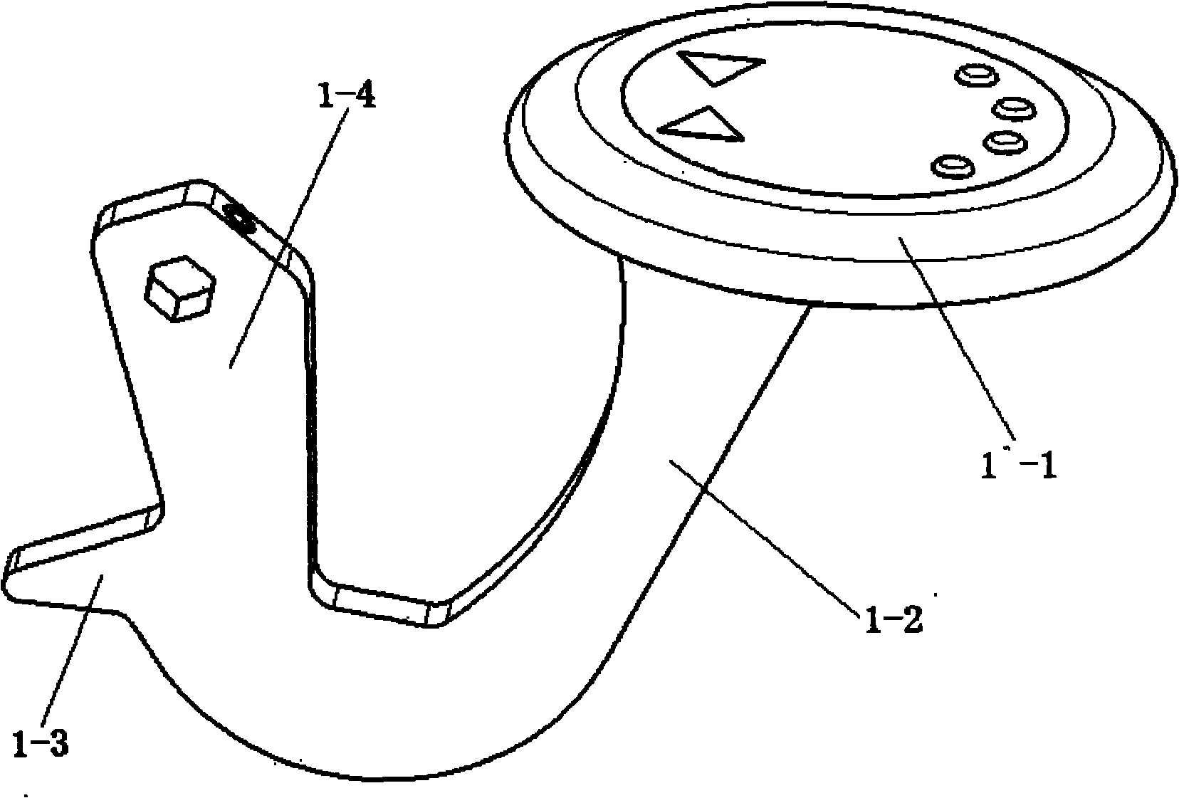
[0014] Such as figure 2 The pedal assembly 1 shown includes a rotating beam 1-4 and a support beam 1-2 supporting the pedal 1-1, and a cross beam 1-3 is arranged at the front end of the rotating beam 1-4.

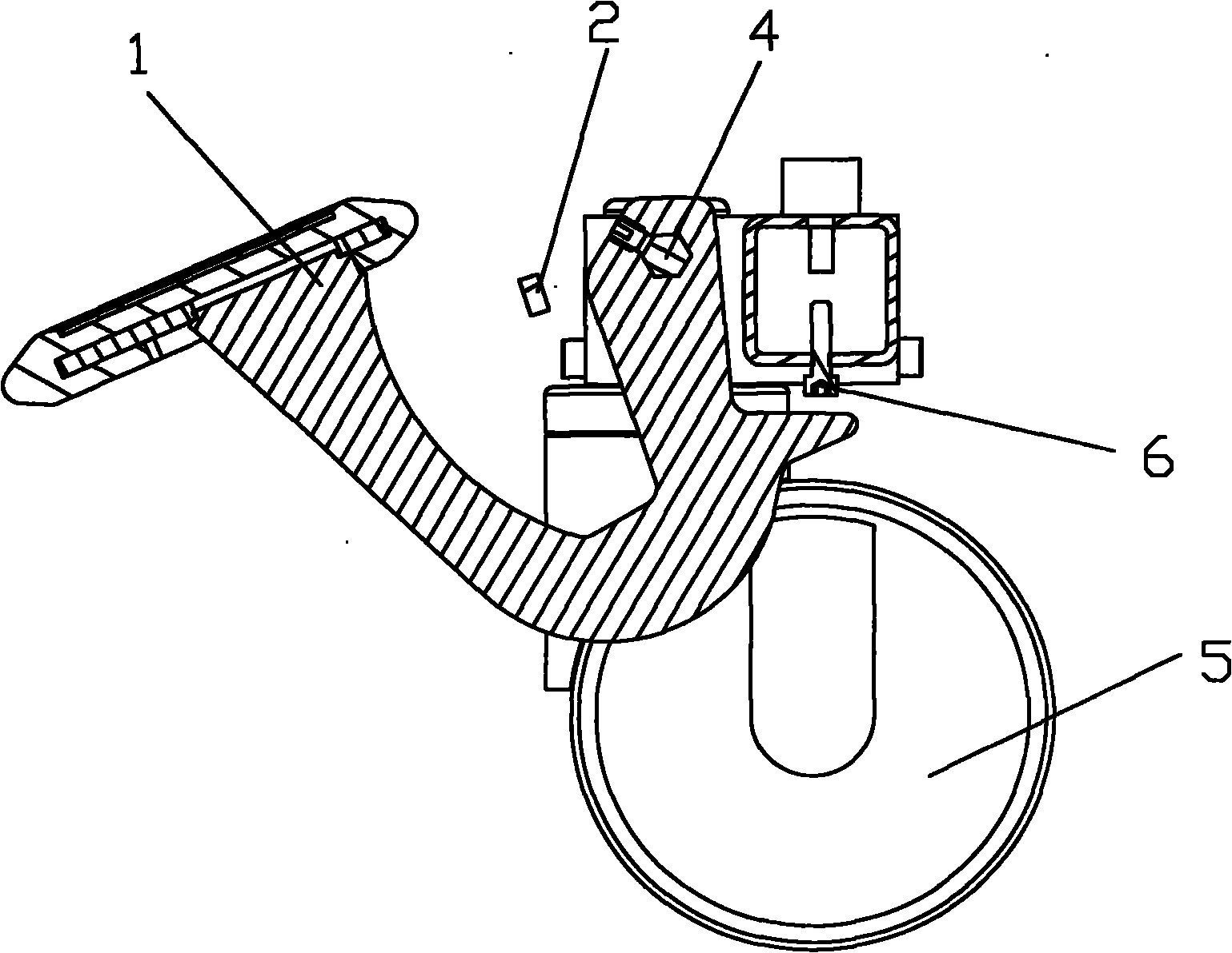
[0015] Such as image 3 The cross-sectional shape of the connecting rod 4 shown is a polygon; the cross-section of the connecting rod 4 is a regular hexagon; the lower part of the bracket 3 directly above the crossbeam 1-3 is provided with a limiting protrusion 6; the rotating A baffle 2 is arranged between the beam 1-4 and the support beam 1-2, and the baffle 2 is fixed on the support 3.

[0016] When the operator steps down on the pedal assembly ...


PUM


Abstract

The invention relates to an integral brake control mechanism for an operating bed. The mechanism comprises a bracket, wherein a universal wheel is arranged on the two sides of the bracket respectively; a connecting rod is arranged between the two universal wheels; and a pedal component is arranged on the connecting rod. The shape of the section of the connecting rod is a polygon, particularly a regular hexagon; the pedal component comprises a rotating beam and a support beam for supporting a pedal; a beam is arranged at the front end of the rotating beam; a limiting bump is formed on the lower part of the bracket which is positioned over the beam; and a baffle plate is arranged between the rotating beam and the support beam and is fixed on the bracket. By using the combination of the pedal component and the connecting rod with the regular hexagonal section, the two universal wheels of the operating bed can be braked at the same time, so that the phenomenon that only one wheel of the operating bed is locked is avoided; and by using the structure of the limiting bump and the baffle plate, the motion range of the pedal component can be effectively limited, so that the damage to the universal wheels is eliminated.

Description

technical field [0001] The invention relates to a parking brake technology for an operating bed, in particular to an integral brake control mechanism for an operating bed. Background technique [0002] Each operating table has four wheels for movement, two of which are fixed-angle wheels and the other two are universal wheels. Only the universal wheels have brakes, and the brakes of each universal wheel work independently. In order to stop the operating table, two universal wheels must be locked simultaneously, and a control device is installed for each universal wheel. But this has disadvantages, if the operator only locks one universal wheel because of negligence in the stop process, then the other universal wheel is in a free state, and the operating table cannot be completely locked. Under the action of external force, the operating table will move. If the movement occurs during the operation, it will lead to unforeseen catastrophic consequences and cause serious medi...

Claims


Application Information

Patent Timeline
IPC IPC(8): A61G13/10
Inventor 彭伟韩洪伟李红强李庆学吉鸣
Owner MAQUET SUZHOU
Why Eureka
Try Eureka