Film attaching method and device

A film sticking device and film sticking technology, which are applied in lamination devices, chemical instruments and methods, electrical components, etc., can solve the problems of unusable film, large waste, waste in the width direction, etc., to improve the quality of the film and improve the quality of the film. , the effect of reducing the likelihood

Inactive Publication Date: 2011-07-13
上海技美科技股份有限公司
View PDF3 Cites 21 Cited by
  • Summary
  • Abstract
  • Description
  • Claims
  • Application Information

AI Technical Summary

Problems solved by technology

In this way, when sticking the film, the pulled out adhesive film 103 just needs to cover the edge of the wafer along the length direction, and there is no waste of the adhesive film along the length direction, but the waste is relatively large along the width direction.
The second situation is that if the width of the adhesive film 103 is smaller than the width of the base 101, then even if the clip 104 is opened, since the adhesive film 103 has been pasted on the wafer 102, the clip 104 returns to the position process before starting to stick the film. , or it will be blocked by the adhesive film attached to the wafer 102; or the two side edges in the width direction of the adhesive film 1

Method used


Image

  • Film attaching method and device
  • Film attaching method and device
  • Film attaching method and device

Examples


Embodiment 1

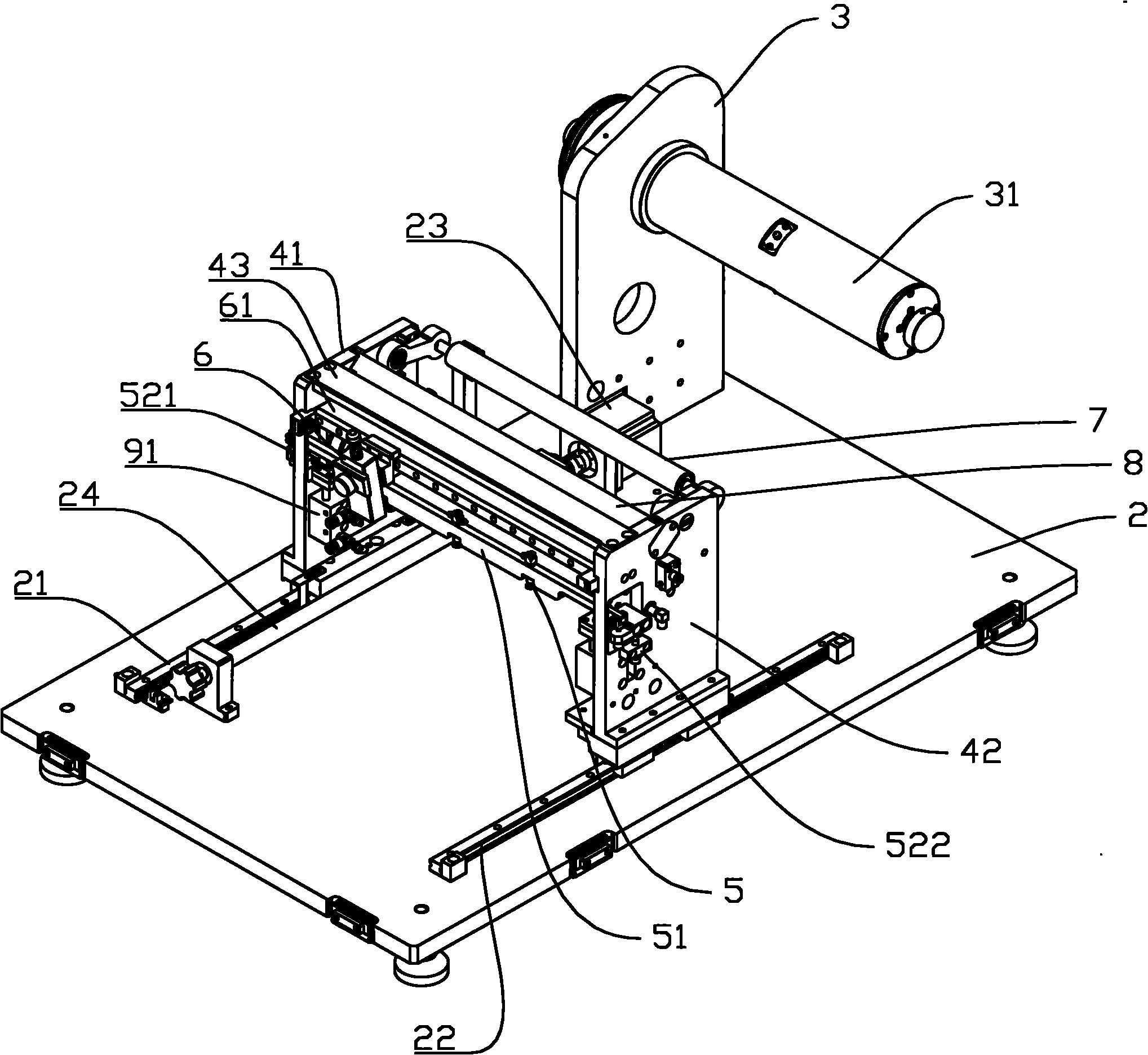
[0054] Film application devices, such as image 3 As shown, it includes a base 2 on which two rack boards (41, 42) are arranged at intervals and in parallel. The lower ends of the two rack plates (41, 42) are provided with guide grooves (not shown in the figure). Two guide rails (21, 22) are arranged on the base 2. The guide rail 21 cooperates with the guide groove at the lower end of the frame plate 41, so that the frame plate 41 can move along the guide rail 21 when driven. The guide rail 22 cooperates with the guide groove at the lower end of the frame plate 42, so that the frame plate 42 can move along the guide rail 22 when driven. The base 2 is provided with a motor 23 and a screw mandrel 24 . The output shaft of the motor 23 is connected with the screw mandrel 24, and the motor 23 can drive the screw mandrel 24 to rotate. The guide rails (21, 22) are horizontally arranged on the base 2, therefore, when the rack boards (41, 42) move, they also move in the horizontal ...

Embodiment 2

[0070] The difference between this embodiment and Embodiment 1 is that the second cross bar 61 , the knife holder 6 and the cutting knife 62 are omitted. When using this embodiment, if the film needs to be cut off, the operator can cut off the film with a cutting knife.

Embodiment 3

[0072] The difference between this embodiment and embodiment 2 is that, on the basis of embodiment 2, the expansion rod is omitted, and the purpose of the present invention can also be achieved.


PUM


Abstract

The invention discloses a film attaching method, which is characterized in that: a film is moved by a vacuum adsorption device, so that the film covers a wafer; and the film is pressed by a pressing device, so that the film is attached to the surface of the wafer. By the method, adhesive films can be saved, procedures are saved, the film attaching efficiency is improved, and the film attaching quality can be improved.

Description

technical field [0001] The invention relates to a film sticking method and a film sticking device. In particular, it relates to a film pasting method and a film pasting device used in the field of semiconductor production. Background technique [0002] Take the wafer attach film as an example, such as figure 1 Shown is a film sticking device, including a base 101 , a table (not shown) for supporting a wafer is provided in the middle of the base 101 , and a wafer 102 is placed on the table of the base 101 . The adhesive film 103 is rolled into a hollow cylinder and is set on a rotatable roller 1031 . The roller 1031 is placed on one side of the base 101 . A clip 104 is installed between the roller 1031 and the base 101 . The working principle of the clip 104 is similar to the clips used in daily life. A roller 105 is installed above the adhesive film 103, and the roller 105 and the clip 104 can move horizontally synchronously. The rollers 105 and the clip 104 can move a...

Claims


Application Information

Patent Timeline
IPC IPC(8): B32B37/10H01L21/00
Inventor 张明星
Owner 上海技美科技股份有限公司
Why Eureka
Try Eureka