
Method and device for adjusting cooling airflow of automotive vehicle

A technology for cooling air and regulating cars, applied in heating/cooling equipment, coolant flow control, mechanical equipment, etc., it can solve the problem of impossible to achieve optimal adjustment of shutters, not taking into account the energy demand of air conditioning, etc., to achieve energy consumption Reduction, minimization of energy consumption, effect of reducing air friction

Inactive Publication Date: 2011-07-13
FORD GLOBAL TECH LLC
View PDF11 Cites 13 Cited by
  • Summary
  • Abstract
  • Description
  • Claims
  • Application Information

AI Technical Summary

Problems solved by technology

The energy demand of the air conditioner, which represents part of the total energy demand of the car, is not taken into account here, so that optimal adjustment of the blinds is not possible when the air conditioner is running

Method used


Image

  • Method and device for adjusting cooling airflow of automotive vehicle
  • Method and device for adjusting cooling airflow of automotive vehicle
  • Method and device for adjusting cooling airflow of automotive vehicle

Examples


Embodiment Construction

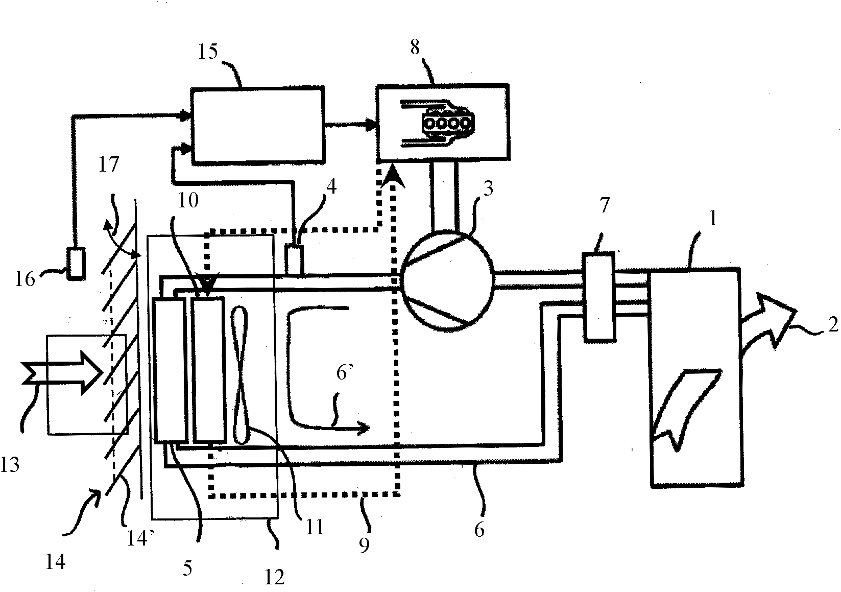
[0042] according to figure 1 An air conditioner installed in a car includes, for example, an internal heat exchanger 1 constituting an evaporator, and the internal airflow 2 passes through the internal heat exchanger 1. The heat given by the internal air to the refrigerant contained in the internal heat exchanger 1 will heat and evaporate the refrigerant, and the internal air will be cooled. The heated or vaporized refrigerant reaches the compressor 3 which compresses the refrigerant. The pressure at the compressor output can be measured by the pressure sensor 4. The compressed refrigerant reaches the outer heat exchanger 5, where it releases part of the heat it contains or condenses. The outer heat exchanger 5 can also be expressed as a liquefier or a condenser, because the gaseous refrigerant can be condensed by releasing heat therein. In the subsequent process of the refrigerant cycle 6, the refrigerant flows through an expansion or decompression device 7, such as a thrott...


PUM


Abstract

The invention relates to a method and a device for adjusting cooling airflow of a motor vehicle, according to the method, when automobile cooling airflow is adjusted, and particularly airflow of an air-conditioner external heat exchanger of an automobile is adjusted, an air-conditioner load parameter and automobile traveling speed are needed to be determined, application of the air-conditioner load parameter and the automobile traveling speed can be used for determining an optimal setting of a flow guide device (14), thereby adjusting cooling airflow to make automobile total energy consumption comprising air-conditioner power consumption be minimized, and the flow guide device (14) controls the cooling airflow according to the determined optimal setting. The invention also relates to a device for adjusting cooling airflow of an automobile.

Description

Technical field [0001] The invention relates to a method and equipment for regulating the cooling air flow of a motor vehicle. Background technique [0002] One or more heat exchangers are usually installed in the front of the car to discharge the heat generated by the engine and other powertrains to the outside world. For this purpose, the dynamic pressure generated by the car during the travel process and possibly the airflow generated by the radiator fan will flow through the one or more heat exchangers and the engine compartment. In an air-conditioned car, under normal circumstances, the external heat exchanger of the air conditioner is installed at the starting radiator part to discharge the heat in the cab to the outside. Here, the air flow through the external heat exchanger is also generated by dynamic pressure and / or one or more fans. [0003] Especially in high-speed travel, the use of dynamic pressure to form a cooling air flow will result in increased air resistance a...

Claims


Application Information

Patent Timeline
Patent Type & Authority Applications(China)
IPC IPC(8): B60K11/08
CPCB60H2001/3277B60H1/3208F01P7/10B60H2001/325
Inventor 马库斯・马科维茨詹姆斯・迈克尔・科恩斯约瑟夫・詹姆斯・盖洛迪特马尔・费舍尔
Owner FORD GLOBAL TECH LLC
Learn More