Supercharge Your Innovation With Domain-Expert AI Agents!

Low-entropy hybrid combustion circulating thermal power system

A thermal power and co-combustion technology, which is applied in the direction of turbine/propellant fuel delivery system, charging system, combustion engine, etc., can solve the problems of energy waste, inability to improve the thermal efficiency of thermal power system, and the problem of emission pollution that cannot be fundamentally solved.

Active Publication Date: 2014-09-10
靖江市红星铜业制造有限公司
View PDF10 Cites 0 Cited by
  • Summary
  • Abstract
  • Description
  • Claims
  • Application Information

AI Technical Summary

Problems solved by technology

However, due to the limitation of the thermodynamic cycle mode of the external combustion engine and the thermodynamic cycle mode of the internal combustion engine, only part of the heat participates in the work cycle in these two cycle systems and also leads to the T of the external combustion cycle system. 1 The value (that is, the temperature of the high-temperature heat source, that is, the temperature of the working medium when it is about to expand and do work) is low and the T of the internal combustion cycle system 2 value (that is, the temperature of the low-temperature heat source, that is, the temperature of the working medium at the end of the expansion stroke / process) is high, which leads to an unsolvable pollution problem, and ultimately causes neither the external combustion engine nor the internal combustion engine to make the thermodynamic system. The thermal efficiency (the ratio of the output work to the calorific value of the fuel) has been substantially improved, and the problem of emission pollution cannot be fundamentally solved
In fact, using these two thermodynamic cycle methods to convert fossil energy and biomass energy into thermal work is not only a huge waste of energy, but also a huge damage to the environment.

Method used


Image

  • Low-entropy hybrid combustion circulating thermal power system
  • Low-entropy hybrid combustion circulating thermal power system
  • Low-entropy hybrid combustion circulating thermal power system

Examples


Embodiment 1

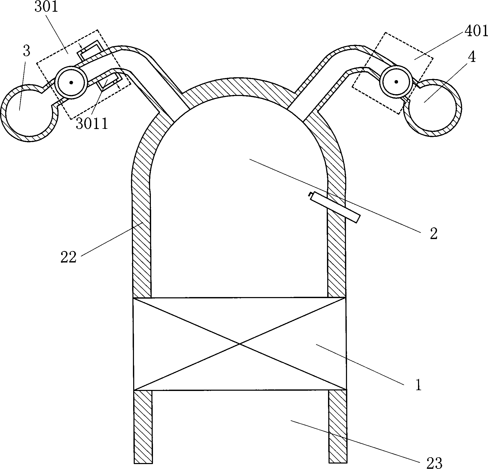
[0130] Such as figure 1 The low-entropy co-combustion cycle thermodynamic system shown includes a working mechanism 1, a combustion chamber 2, an oxygen source 3 and a fuel source 4, the oxygen source 3 communicates with the combustion chamber 2 through an oxygen high-pressure supply system 301, and the fuel source 4 passes through The fuel high-pressure supply system 401 communicates with the combustion chamber 2, and an oxygen heat-absorbing heat exchanger 3011 is installed in the oxygen high-pressure supply system 301, and the oxygen in the oxygen source 3 absorbs heat in the oxygen heat-absorbing heat exchanger 3011 to form high-pressure gaseous oxygen Entering the combustion chamber 2, the minimum pressure bearing capacity of the oxygen high-pressure supply system 301 is greater than or equal to 2MPa; the combustion chamber 2 communicates with at least one working mechanism 1, and the working mechanism 1 outputs power to the outside. The oxygen source 3 is set as a cryog...

Embodiment 2

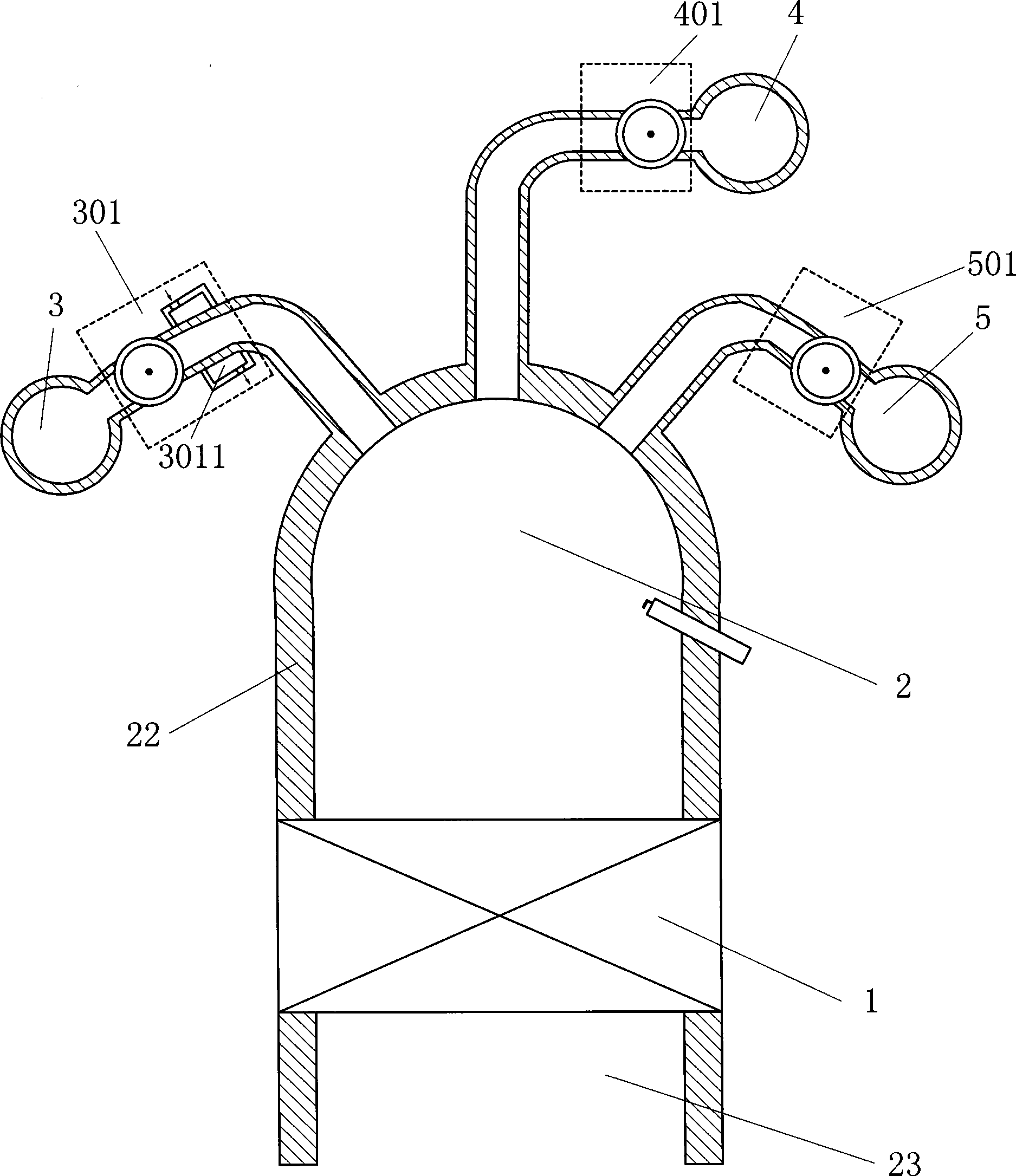
[0132] Such as figure 2 The low-entropy co-combustion cycle thermodynamic system shown includes a working mechanism 1, a combustion chamber 2, an oxygen source 3, a fuel source 4 and an expansion agent source 5, and the oxygen source 3 communicates with the combustion chamber 2 through an oxygen high-pressure supply system 301 , the fuel source 4 communicates with the combustion chamber 2 through the fuel high-pressure supply system 401, and the expansion agent source 5 communicates with the combustion chamber 2 through the expansion agent high-pressure supply system 501; an oxygen heat-absorbing heat exchanger is set in the oxygen high-pressure supply system 301 3011, the oxygen in the oxygen source 3 absorbs heat in the oxygen heat-absorbing heat exchanger 3011 to form high-pressure gaseous oxygen and enters the combustion chamber 2; the minimum pressure bearing capacity of the oxygen high-pressure supply system 301 and / or the expander high-pressure supply system 501 is grea...

Embodiment 3

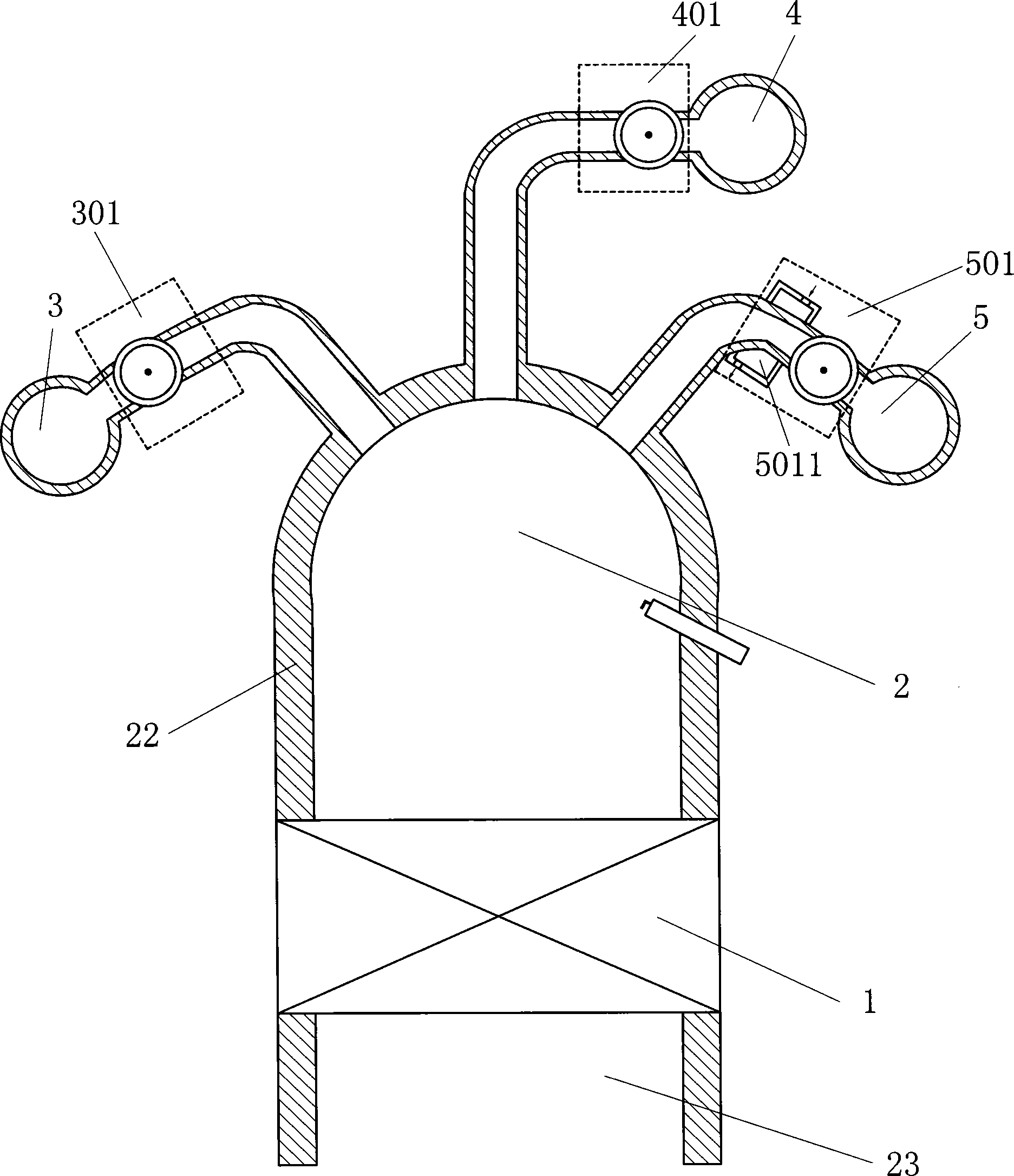
[0134] Such as image 3 The low-entropy co-combustion cycle thermodynamic system shown includes a working mechanism 1, a combustion chamber 2, an oxygen source 3, a fuel source 4 and an expansion agent source 5, and the oxygen source 3 communicates with the combustion chamber 2 through an oxygen high-pressure supply system 301 , the fuel source 4 communicates with the combustion chamber 2 through the fuel high-pressure supply system 401, and the expansion agent source 5 communicates with the combustion chamber 2 through the expansion agent high-pressure supply system 501; Exchanger 5011, the expansion agent in the expansion agent source 5 absorbs heat in the expansion agent heat-absorbing heat exchanger 5011 to form a high-pressure gaseous expansion agent and enters the combustion chamber 2; the oxygen high-pressure supply system 301 and / or the expansion agent high-pressure supply system 501 The minimum pressure bearing capacity is greater than or equal to 4MPa; the combustion...


PUM


Abstract

A low-entropy mixed combustion circulating thermal power system includes a working mechanism (1), a combustion chamber (2), an oxygen source (3), a fuel source (4) and an expansion agent source (5). The oxygen source (3) is communicated with the combustion chamber (2) through an oxygen high-pressure supply system (301), the fuel source (4) is communicated with the combustion chamber (2) through a fuel high-pressure supply system (401) and the expansion agent source (5) is communicated with the combustion chamber (2) through an expansion agent high-pressure supply system (501). An oxygen heat absorption heat exchanger (3011) is arranged in the oxygen high-pressure supply system (301) and the oxygen in the oxygen source (3) absorbs heat in the oxygen heat absorption heat exchanger (3011) to form a high-pressure gaseous oxygen. Then the high-pressure gaseous oxygen enters into the combustion chamber (2). An expansion agent heat absorption heat exchanger (5011) is arranged in the expansion agent high-pressure supply system (501) and the expansion agent in the expansion agent source (5) absorbs heat in the expansion agent heat absorption heat exchanger (5011) to form a high-pressure gaseous expansion agent. Then high-pressure gaseous expansion agent enters into the combustion chamber (2). The minimal pressure bearing capability of the oxygen high-pressure supply system (301) is greater than or equal to 2MPa, and the combustion chamber (2) is connected with the working mechanism (1) outputting power. The low-entropy mixed combustion circulating thermal power system realizes high efficiency, energy saving and low emission.

Description

technical field [0001] The invention relates to the field of thermal energy and power, in particular to a low-entropy co-combustion cycle thermal power system. Background technique [0002] In 1769, the birth of the external combustion engine directly triggered the first industrial revolution of mankind, and also created Great Britain, an empire on which the sun never sets. The birth of the gasoline engine in 1883 and the birth of the diesel engine in 1897 marked the beginning of mankind's transition from the era of external combustion to the era of internal combustion. Internal combustion engines represented by gasoline engines and diesel engines have built the power foundation of modern civilization and carried countless dreams of human beings. It can be seen that both external combustion engines and internal combustion engines have made immeasurable contributions to the progress of human civilization. Today, a country's internal combustion and external combustion engine...

Claims


Application Information

Patent Timeline
Patent Type & Authority Patents(China)
IPC IPC(8): F02G5/04F02M25/00F02B23/00F02C3/14F02M25/10F02M31/18F02C7/224F02C3/24
CPCY02T10/166Y02T10/125Y02E20/344Y02E20/322F23R3/005Y02T10/126F23L7/007F02B47/06F02M31/163Y02T10/121F02M25/00F02B41/02F23R3/42Y02E20/34Y02T10/12
Inventor 靳北彪
Owner 靖江市红星铜业制造有限公司
Features
  • R&D
  • Intellectual Property
  • Life Sciences
  • Materials
  • Tech Scout
  • Unparalleled Data Quality
  • Higher Quality Content
  • 60% Fewer Hallucinations
Learn More