
Robot system having positioner

A robot system and positioner technology, applied in the field of robot systems, can solve the problems of larger working space, larger factory space, and higher air-conditioning costs, and achieve the effect of reducing air-conditioning costs.

Inactive Publication Date: 2011-07-20
YASKAWA DENKI KK
View PDF12 Cites 0 Cited by
  • Summary
  • Abstract
  • Description
  • Claims
  • Application Information

AI Technical Summary

Problems solved by technology

[0005] Although the existing robot system builds a production line in which the work object is sequentially transferred to the work process while using the robot and the positioner to weld the work object, but because the positioner is arranged in the working area of ​​the robot , so the space for setting up the positioner and the space for setting up the robot are required separately, resulting in the problem that the working space becomes larger accordingly, and the factory space becomes larger, resulting in the problem that the cost of the air conditioner increases accordingly

Method used


Image

  • Robot system having positioner
  • Robot system having positioner
  • Robot system having positioner

Examples


Embodiment 1

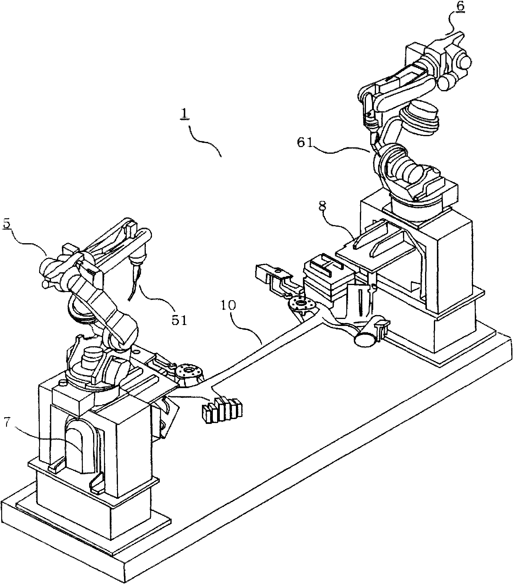
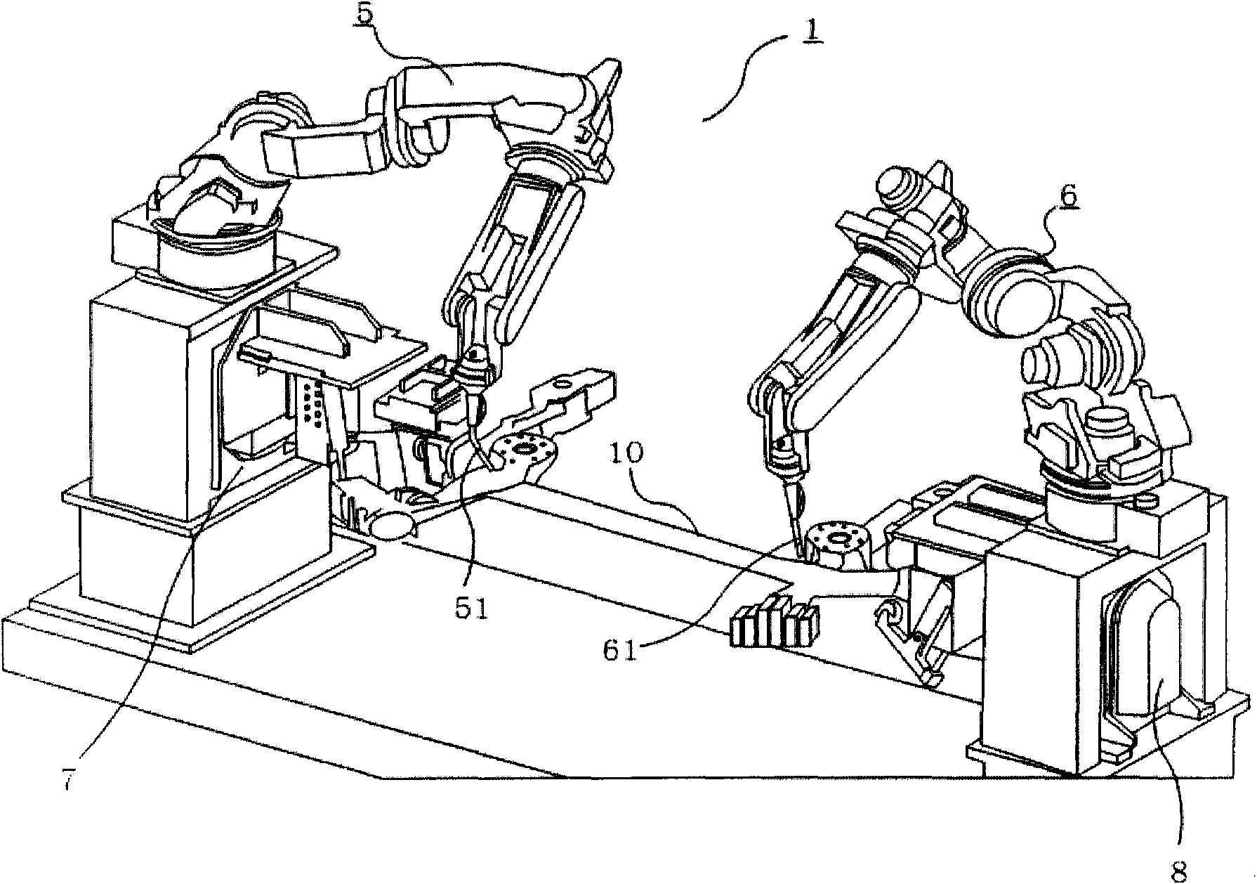
[0021] Such as figure 1 As shown, the work object 10 is, for example, a long-sized object such as a chassis of an automobile, and is attached to the first positioner 7 and the second positioner 8 in the first welding process by a transfer robot (not shown). Next, the first positioner 7 and the second positioner 8 are rotated so as to align with the welding position, and the first welding robot 5 and the second welding robot 6 weld a predetermined position. When the welding is completed, the transfer robot 9 is placed on a not-shown workbench. Next use figure 1 and figure 2 The first welding process will be described in detail as an example. figure 1 is a perspective view of the welding robot when it is in the standby position, figure 2 It is a perspective view during welding. Such as figure 1 As shown, in the first welding process 1, the first welding robot 5 and the second welding robot 6 are arranged on the first positioner 7 and the second positioner 8, respectively...


PUM


Abstract

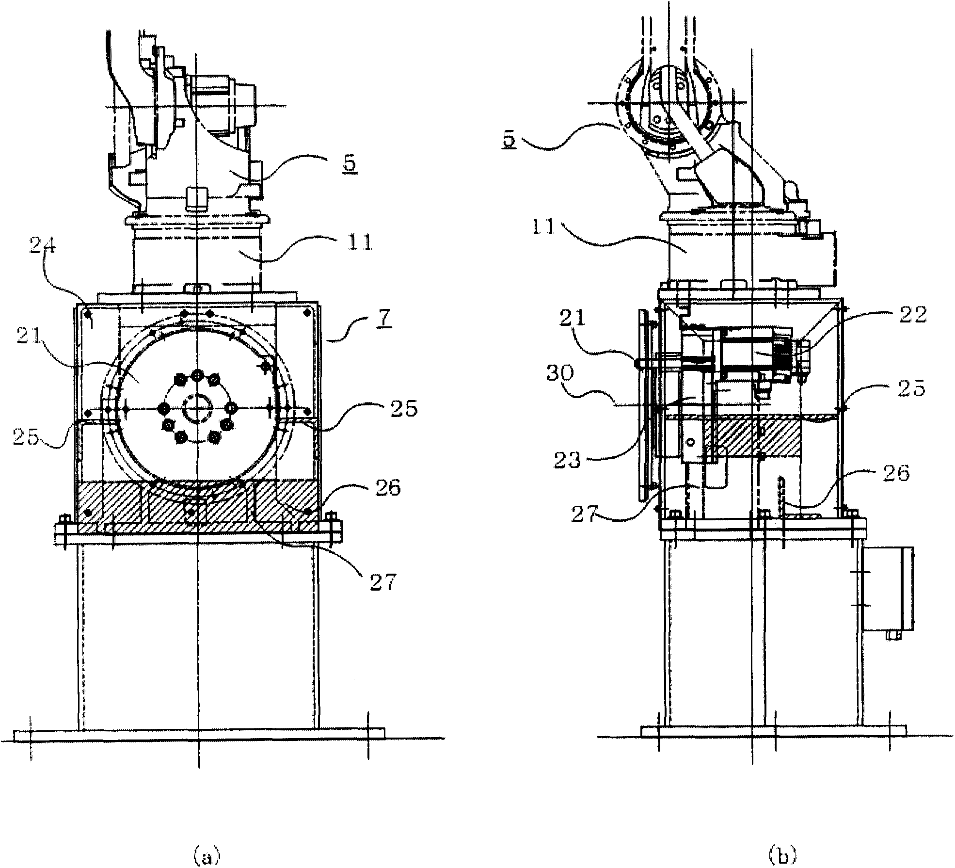
The present invention provides a robot system which uses robots and positioners for reducing an occupied area. The robot system is provided with the following components: a work object (10); robots (5,6) that carry out work on the work object (10); and positioners (7,8) which position the work object, wherein the frame (24) of the positioners (7,8) are provided with the robots (5,6).

Description

technical field [0001] The present invention relates to a robot system in which a robot is mounted on a positioner. Background technique [0002] In recent years, in a production line using industrial robots, there is a tendency to reduce the manufacturing process by densely arranging robots. That is, by reducing the occupied area of ​​the robot and making the factory itself smaller, the air-conditioning equipment can be made smaller while reducing the cost required for factory air-conditioning. In addition, since the tact time can be improved by shortening the distance between work processes, it is required to reduce the manufacturing process. [0003] As a typical example of a production line including such a manufacturing process, a welding line for automobile parts and the like can be cited. As a conventional welding line system, a system using a robot and a positioner for positioning components has been proposed (for example, refer to Patent Document 1). [0004] Pat...

Claims


Application Information

Patent Timeline
IPC IPC(8): B25J9/10B25J19/00B23K37/02
CPCB25J9/0084B25J9/0096
Inventor 白神圭祐原胜明中野光善
Owner YASKAWA DENKI KK
Learn More