Temperature control system for machine tool

a technology of temperature control system and machine tool, which is applied in the direction of lighting and heating apparatus, heating types, instruments, etc., can solve the problems of inability to perform satisfactory temperature control, large heat capacity of the machine tool mechanical section b>2/b>, and inability to cope with substantial temperature change around the machine tool controller. , to achieve the effect of reducing the cost of air conditioning around the machine tool, improving controllability, and constant temperature of the machine tool mechanical section

Inactive Publication Date: 2011-01-25
FANUC LTD
View PDF2 Cites 1 Cited by
  • Summary
  • Abstract
  • Description
  • Claims
  • Application Information

AI Technical Summary

Benefits of technology

[0015]The present invention provides a temperature control system for a machine tool, capable of quickly responding to an ambient temperature change with a reduced time constant for a temperature sensor portion, that is, with improved response to heating, based on the respective temperatures of gas in the machine tool and gas supplied to gas bearings.
[0019]According to the present invention, the temperature sensor detects temperature around the mechanical section and the temperature detection by the temperature sensor is influenced by temperature of the gas discharged from the temperature controller by introducing a part of the gas discharged from the temperature controller directly to the temperature sensor. Thus, the controllability is improved so that the temperature of the machine tool mechanical section can be kept constant. In consequence, the cost of air conditioning around the machine tool can be reduced.
[0020]According to the present invention, moreover, temperature sensors for controlling the temperature of the machine tool mechanical section to be constant need not be increased in number, so that the temperature control system is not complicated.

Problems solved by technology

However, the controller 6 cannot cope with a substantial temperature change around the machine tool 1.
In general, however, the heat capacity of the machine tool mechanical section 2 is very large.
Thus, satisfactory temperature control cannot be performed if the time constant is so large that the heat capacity of the machine tool mechanical section 2 is too large for the gas.
Thus, the temperature change of the mechanical section 2 cannot be suppressed, that is, an original purpose cannot be achieved.
However, the temperature control of the machine tool mechanical section is difficult mainly because the temperature of the machine tool depends on both the respective temperatures of air inside the machine tool cover and the gas for the gas bearings, and because both these temperatures influence each other in a ratio appropriate to each individual machine tool.

Method used


Image

  • Temperature control system for machine tool
  • Temperature control system for machine tool
  • Temperature control system for machine tool

Examples


Embodiment Construction

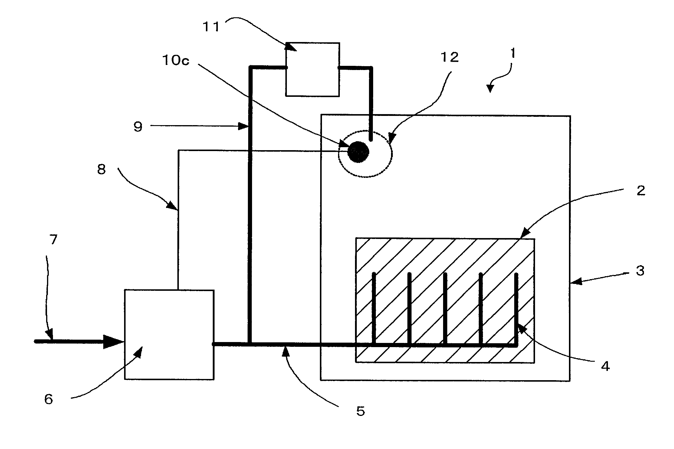
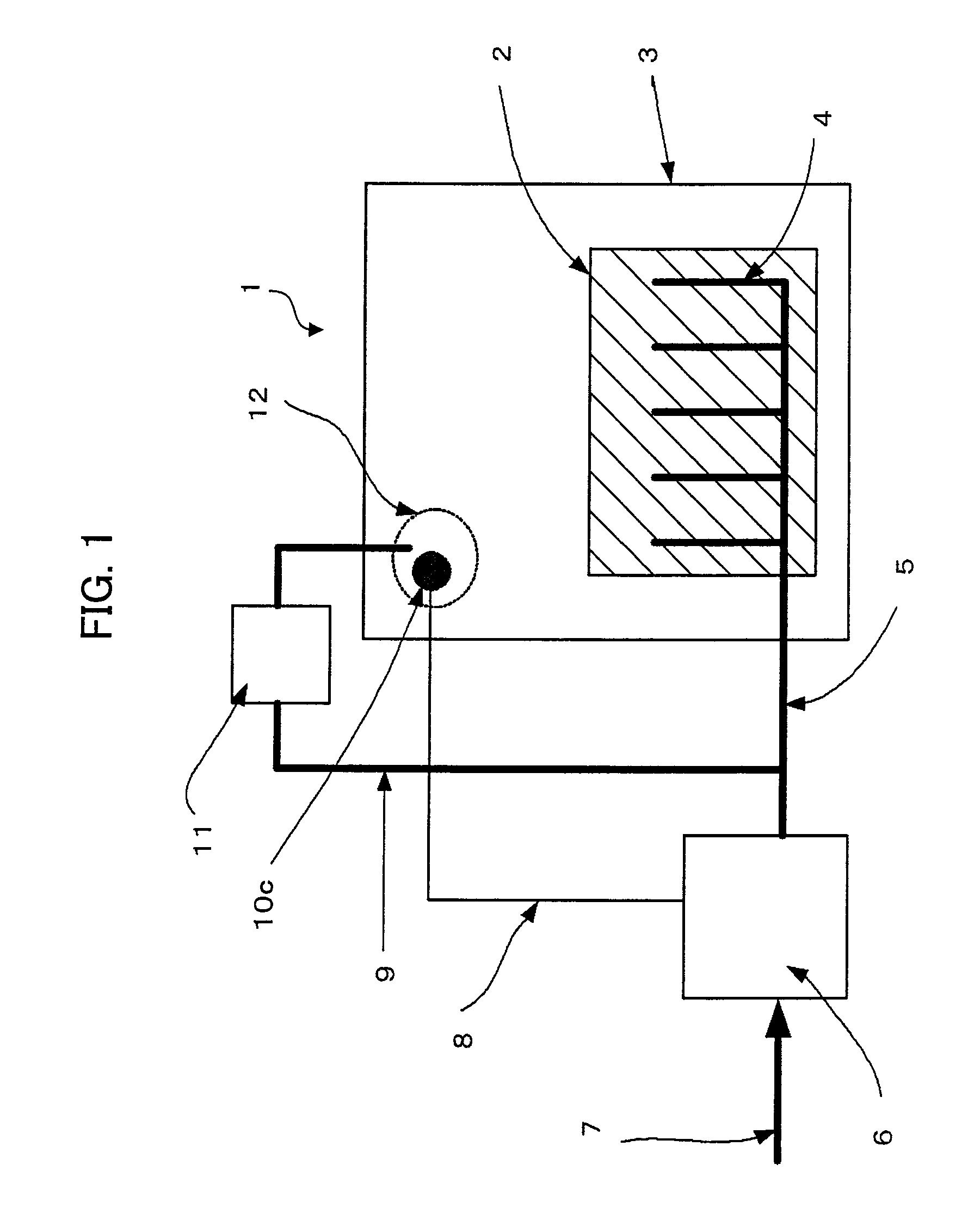
[0029]FIG. 1 is a diagram showing one embodiment of a temperature control system of the present invention. A machine tool 1 of this embodiment includes a machine tool mechanical section 2 for ultra-precision machining as a temperature control object. Normally, in performing ultra-precision, the machine tool is installed in an air-conditioned room, as shown in FIG. 8.

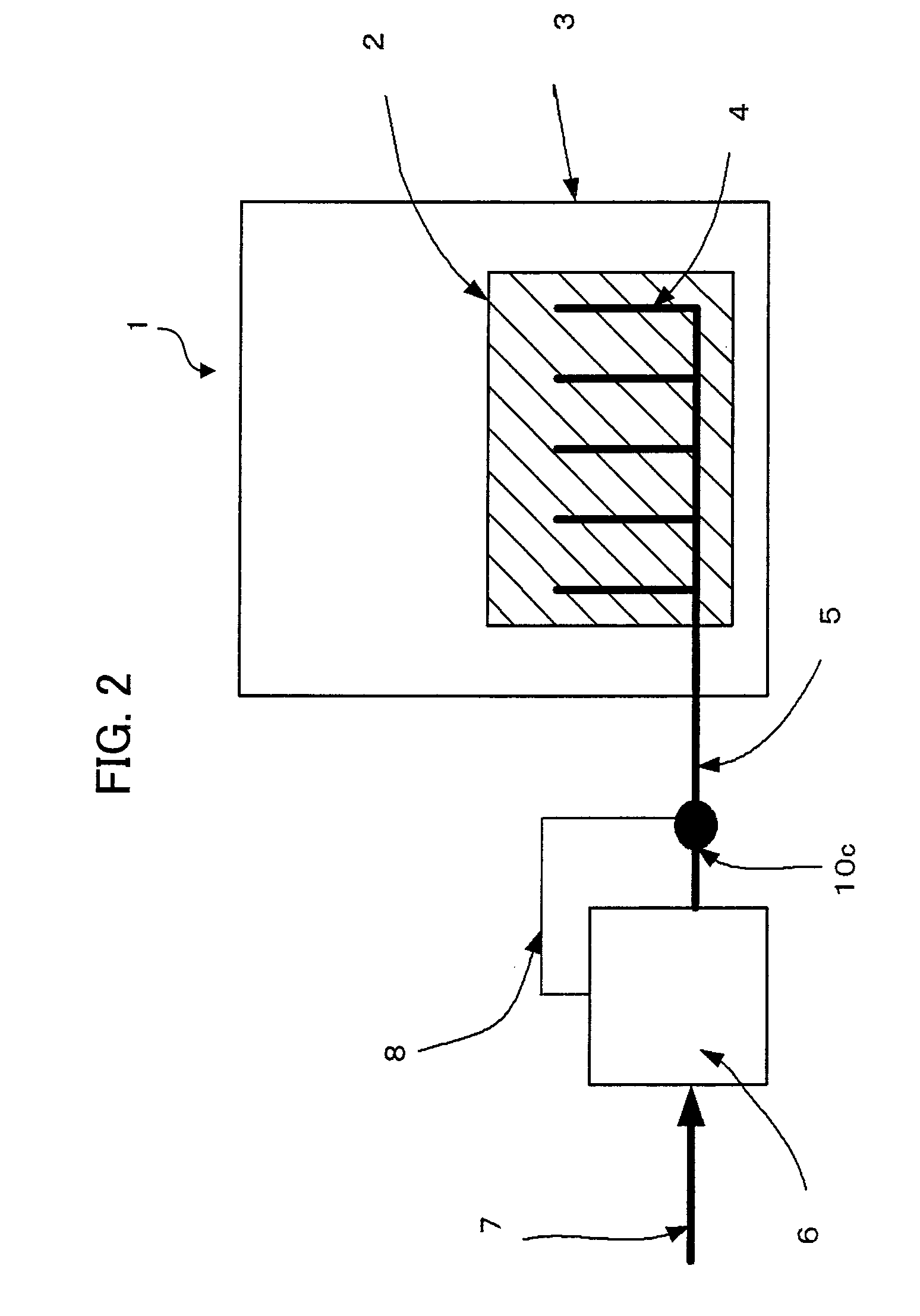
[0030]The machine tool 1 is provided with the machine tool mechanical section 2 and a machine tool cover 3 that covers it. The machine tool mechanical section 2 is surrounded by the machine tool cover 3, and the interior of the mechanical section 2 is networked with a gas bearing channel 4. Gas (e.g., air) from the gas bearing channel 4 is supplied to gas bearings (not shown). A temperature controller 6 is supplied with gas 7 such as air that is compressed by a compressor (see FIG. 8). The gas 7 that is subjected to temperature-control by the temperature controller 6 is discharged from bearing portions (not shown) of the...


PUM

PropertyMeasurementUnit
temperatureaaaaaaaaaa
heat capacityaaaaaaaaaa
temperaturesaaaaaaaaaa

Abstract

A temperature control system for a machine tool capable of quickly responding to an ambient temperature change. A mechanical section of the machine tool is surrounded by a machine cover. Gas of which temperature is controlled by a temperature controller is discharged from bearing portions of gas bearings in the mechanical section to a region surrounded by the machine cover through a pipe and a gas bearing channel. A branch pipe is provided for directly introducing a part of gas discharged from the temperature controller to a temperature sensor inside the machine cover. The temperature sensor measures the temperature of gas mixture obtained by mixing the gas introduced directly from the pipe with air inside the machine cover in a predetermined ratio. The result of measurement by the temperature sensor is fed back to the temperature controller to control the temperature of the gas supplied to the gas bearings.

Description

RELATED APPLICATIONS[0001]The present application is based on, and claims priority from, Japanese Application Number 2007-194213, filed Jul. 26, 2007, the disclosure of which is hereby incorporated by reference herein in its entirety.BACKGROUND OF THE INVENTION[0002]1. Field of the Invention[0003]The present invention relates to a temperature control system for a machine tool that performs nanometer-order machining.[0004]2. Description of Related Art[0005]In an ultra-precision machine, such as a machine tool or a measuring device for nanometer-order machining or measurement, the ambient temperature influences the machining accuracy and measurement accuracy, thereby changing the machined or measured shape. High-precision temperature control is needed to suppress the influence of the ambient temperature.[0006]In a machine tool shown in FIG. 8, the interior of a mechanical section 2 is networked with a channel for gas bearings. For precision machining, the mechanical section 2 and a co...

Claims


Application Information

Patent Timeline
Patent Type & Authority Patents(United States)
IPC IPC(8): F24F11/053B23Q11/12F24F3/00G05D23/12F24F11/76
CPCB23Q11/143B23Q11/145Y10T409/303976Y10S82/90
Inventor KAWAI, TOMOHIKOEBIHARA, KENZOMINAMI, HIROSHI
Owner FANUC LTD
Why Eureka
Try Eureka