Floor plate connector and floor plate connection structure

A technology for connecting structures and connecting parts, applied in the field of building decoration materials, can solve problems such as crack expansion at joints, and achieve the effects of reliable sealing, difficult displacement and convenient assembly.

Inactive Publication Date: 2011-07-20
李增清
View PDF0 Cites 6 Cited by
  • Summary
  • Abstract
  • Description
  • Claims
  • Application Information

AI Technical Summary

Problems solved by technology

[0004] The purpose of the present invention is to solve the problem that the connection of two adjacent transverse sides of the traditional decking, especially the floor, will inadvertently displace along the common joint, causing the cracks at the joint to expand
[0005]

Method used


Image

  • Floor plate connector and floor plate connection structure
  • Floor plate connector and floor plate connection structure
  • Floor plate connector and floor plate connection structure

Examples


Embodiment 1

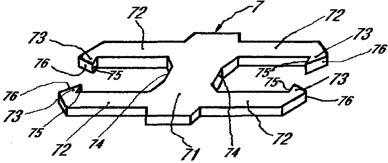
[0026] Embodiment 1: as figure 1 As shown, a deck connector 7 includes a mother body 71 and a pair of inserting arms 72 are arranged symmetrically on both sides of the mother body 71. The inserting arms 72 are parallel to each other and extend outward from the mother body 71. The inserting arms 72 An outwardly protruding card body 73 is formed on the free end, and the free ends of the inserting arms 72 can move elastically with each other. The card body 73 on the insertion arm 72 on the same side of the mother body 71 is arranged opposite to each other. The card body 73 is formed with two sides, one of which is formed with a first slope 76 extending limitedly from the end of the card body to the direction of the mother body. One side is formed with a first contact surface 75 capable of engaging with the surface of other objects; the two sides of the mother body 71 between the two inserting arms 72 form a second contact surface 74 respectively. Two opposite first slopes 76 for...

Embodiment 2

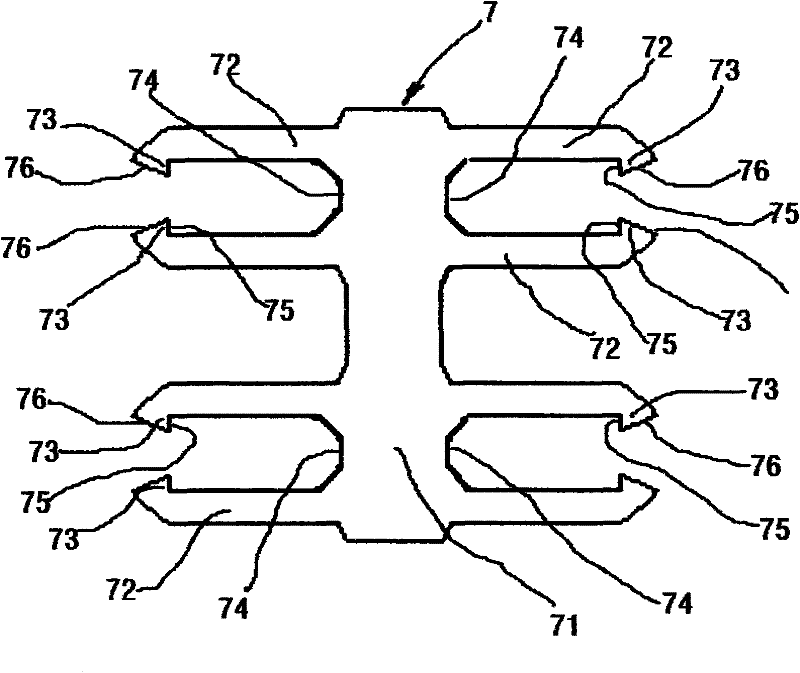
[0027] Embodiment 2: as figure 2 As shown, it is illustrated that a number of inserting arms 72 can be arranged on both sides of a mother body 71 according to the actual situation, but at least one pair of inserting arms 72 have card bodies 73 opposite to each other. Such as figure 2 As shown, two pairs of inserting arms 72 are arranged symmetrically on both sides of the mother body 71 , and the card bodies 73 on the ends of at least one pair of inserting arms 72 are oppositely arranged.

Embodiment 3

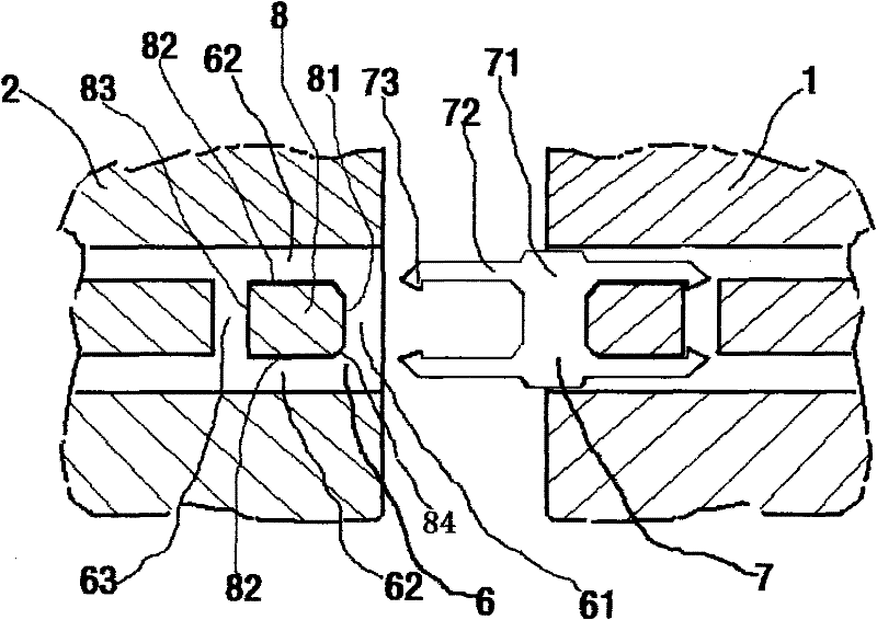
[0028] Embodiment 3: as image 3In the decking connection structure shown, the adjacent first decking 1 and second decking 2 are connected through the decking connector 7, and the respective side ports of the decking 1 and the decking 2 are respectively provided with the corresponding joints of the decking connector 7. Adapted connection groove 6, the connection groove 6 is composed of a mother groove 61, a card body groove 63 and two parallel insertion grooves 62, and the plank formed by them partially forms a support part 8, and the support part 8 faces the card body One side of the groove 63 forms a first abutting surface 83, the side facing the matrix groove 61 forms a second abutting surface 81, and the side facing the insertion groove 62 forms a third abutting surface 82; the second abutting surface 81 A chamfered second inclined surface 84 is formed at the junction with the third abutting surface 82 . Half of the connecting piece 7 is first inserted into the connecting...


PUM


Abstract

The invention relates to a floor plate connector and a floor plate connection structure, belonging to the technical field of building decoration materials. The floor plate connector comprises a plurality of splicing arms and a master body connected with the plurality of splicing arms; at least one side of the master body is provided with a plurality of splicing arms, which are parallel to each other and extend to the outside of the master body; a clamping body protruding outwards is arranged on the free end part of each splicing arm; and at least one pair of clamping bodies arranged on the splicing arms on the same side of the master body are arranged opposite to each other. For the design of the floor plate connection structure, two adjacent transverse sides of every two adjacent floor plates are connected through the floor plate connector, the lower surfaces of transverse side ports of the floor plates are respectively provided with a connection groove adaptive to the structure of the floor plate connector, each connection groove comprises a pair of parallel and symmetrical splicing grooves as well as a master body groove and a clamping body groove which are communicated with the two splicing grooves, and the splicing grooves and the clamping body grooves are used for accommodating the splicing arms on the floor plate connector, wherein the clamping bodies on the splicing arms are hooked and clamped inside the clamping body grooves, and the master body grooves are used for accommodating the master body on the floor plate connector.

Description

technical field [0001] The invention relates to a decking connector and a decking connection structure, belonging to the technical field of building decoration materials. technical background [0002] Traditional planks, especially floors, are joined by tongue and groove with a press fit or form fit. Planks joined to each other in this way may inadvertently shift along the common edge of the joint, which can lead to problems during laying. Unintentional inaccuracies appear. As a result of the unintentional displacement, any cracks formed at the joint are thus also enlarged, and it is moreover difficult to provide a seal at this type of joint. Dirt collects in these cracks, or water can penetrate at this location, thereby causing the core of the plank to swell. As a result, cracks will increase and stress will increase in this surface area, reducing the lifetime of the overall plank. In order to prevent these planks, especially the floors, from being displaced along the co...

Claims


Application Information

Patent Timeline
IPC IPC(8): E04F13/21E04F15/02
Inventor 李增清
Owner 李增清
Why Eureka
Try Eureka