Fuel supply system

A fuel supply system and fuel supply technology, applied in the direction of charging system, liquid fuel feeder, engine components, etc., can solve problems such as difficult to function

Inactive Publication Date: 2011-07-20
COAVIS
View PDF5 Cites 8 Cited by
  • Summary
  • Abstract
  • Description
  • Claims
  • Application Information

AI Technical Summary

Problems solved by technology

[0012] Therefore, if Figure 1 to Figure 3 As shown, the filtration efficiency is improved in terms of the amount of returned fuel reac

Method used


Image

  • Fuel supply system
  • Fuel supply system
  • Fuel supply system

Examples


Embodiment Construction

[0038] Advantages, features and aspects of the present invention will be better understood through the following description of embodiments set forth hereinafter with reference to the accompanying drawings.

[0039] The invention may be embodied in different forms and should not be construed as limited to the embodiments set forth herein. Rather, these embodiments are provided so that this disclosure will be thorough and complete, and will fully convey the scope of the invention to those skilled in the art.

[0040] Next, a fuel supply system having the above components will be described with reference to the accompanying drawings.

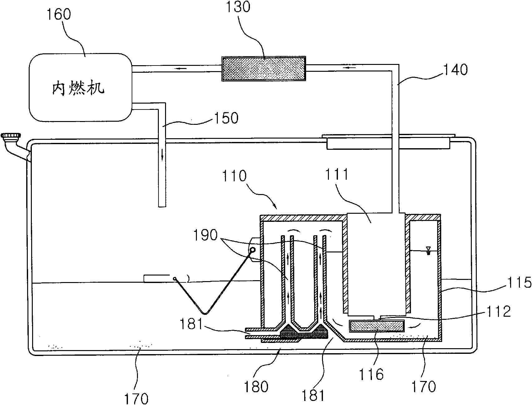
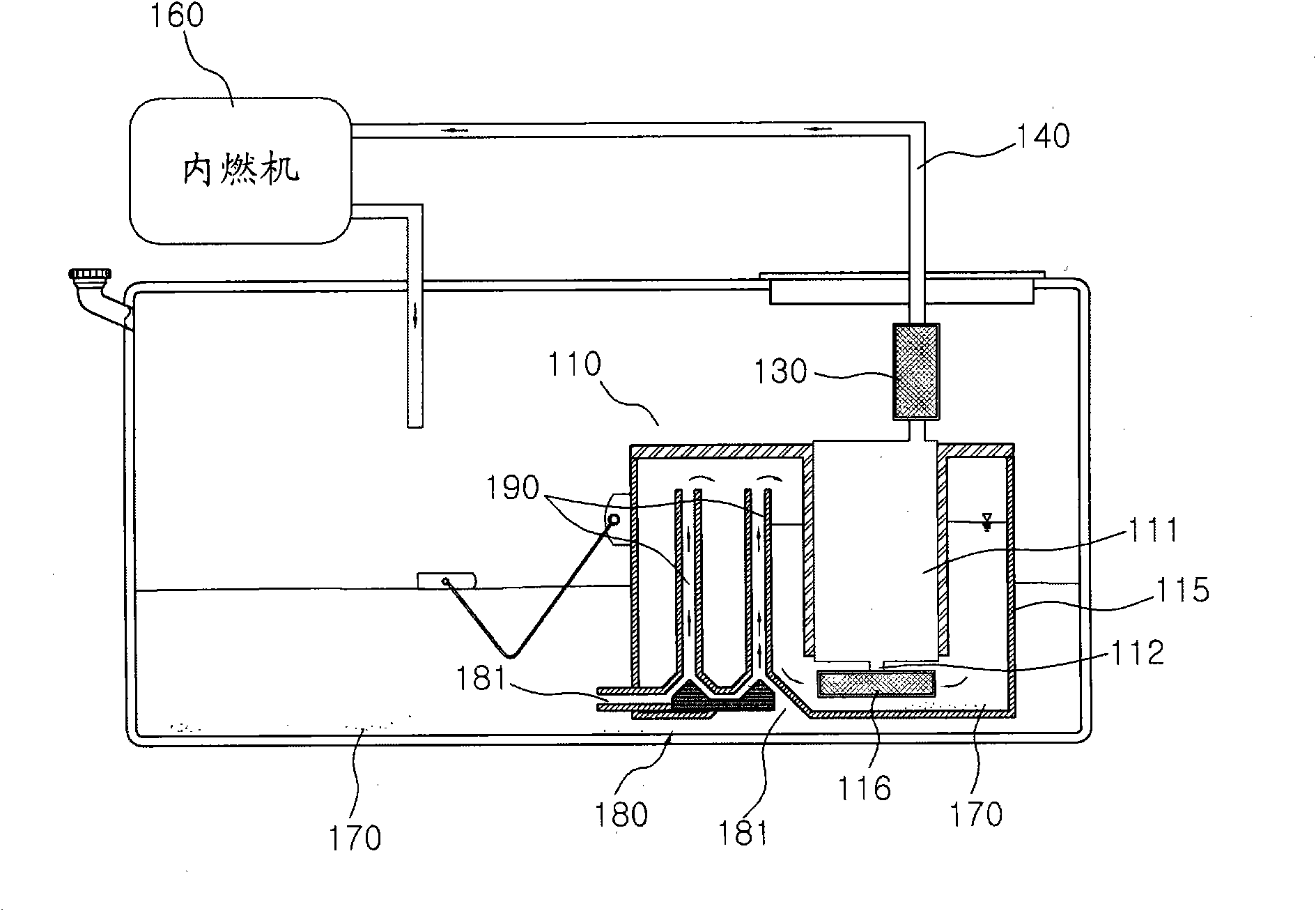
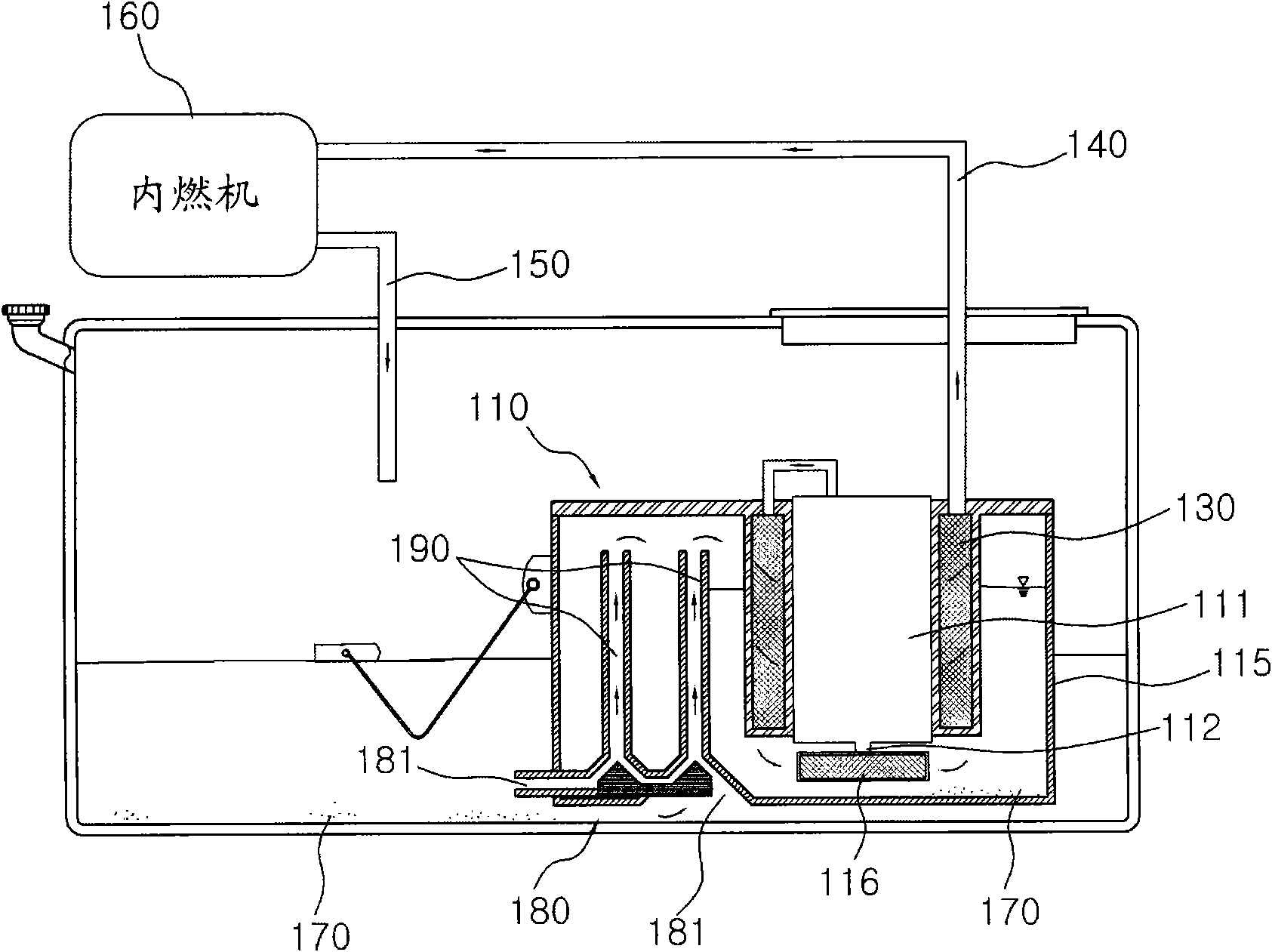
[0041] Figure 7 is a schematic diagram of a type A fuel supply system according to the present invention, Figure 8 is a schematic diagram of a Type B fuel supply system according to the present invention, Figure 9 is a schematic diagram of a Type C fuel supply system according to the present invention, and Figure 10 is a schematic diagram ...


PUM


Abstract

Provided is a fuel supply system. The fuel supply system includes a fuel pump module mounted in a fuel tank and including a reservoir having a predetermined amount of fuel filled therein and a fuel pump mounted in the reservoir to suck the fuel filled in the reservoir and supply it to an internal combustion engine; a fuel supply line supplying fuel from the fuel pump module to the internal combustion engine; and a fuel return line returning the fuel from the internal combustion engine to the fuel tank, wherein the inside of the reservoir is provided with a bypass tube connecting the fuel return line to the fuel pump to directly supply the fuel returned through the fuel return line to the fuel pump through the bypass tube.

Description

[0001] Related Application Cross Reference [0002] This application claims priority under 35 U.S.C. Section 119 to Korean Patent Application No. 10-2010-0003768 filed in the Korean Intellectual Property Office on January 15, 2010, the disclosure of which is incorporated herein by reference. technical field [0003] The present invention relates to a fuel supply system capable of supplying fuel to an internal combustion engine and returning fuel from the internal combustion engine to a fuel tank, and more particularly the present invention relates to a fuel supply system capable of feeding fuel through The fuel from which impurities are removed by various filters is used in the internal combustion engine, and the remaining fuel is directly supplied to the fuel filter, thereby supplying cleaner fuel to the internal combustion engine, and using the returned fuel as a working fluid during fuel supply to increase the fuel pump durability. Background technique [0004] Generally...

Claims


Application Information

Patent Timeline
IPC IPC(8): F02M37/22F02M37/06
CPCF02M37/025F02M2037/225F02M37/106F02M2037/228F02M37/44F02M37/50
Inventor 林宗根孙寅硕申奎燮金俊燮全文植
Owner COAVIS
Why Eureka
Try Eureka