
Focus controlling device for a beam projector

A focus control and projector technology, which is applied to the focus device of the camera, the focus device of the projector, the focus device, etc., and can solve the problems such as restrictions imposed by the external design of the entire design of the portable terminal

Inactive Publication Date: 2011-07-20
SAMSUNG ELECTRONICS CO LTD
View PDF0 Cites 7 Cited by
  • Summary
  • Abstract
  • Description
  • Claims
  • Application Information

AI Technical Summary

Problems solved by technology

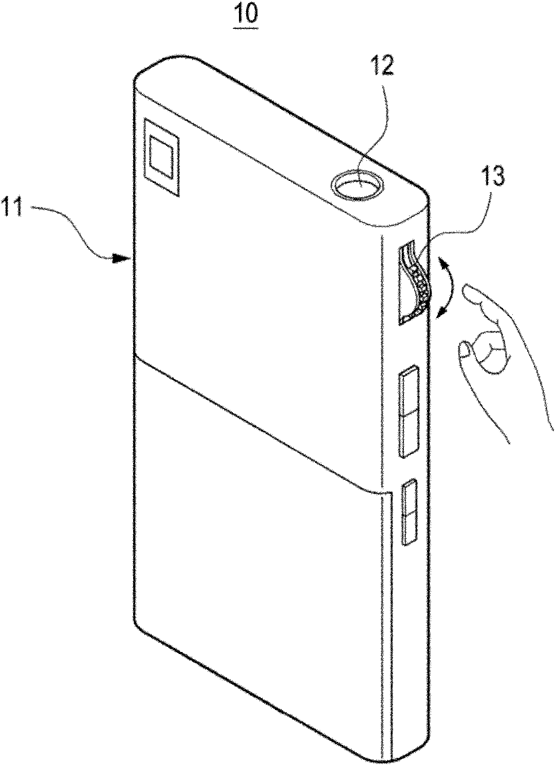
[0010] However, since the focus control device for the beam projector is installed on the upper part of the main body 11 in the conventional portable terminal, it imposes restrictions on the overall design or at least the external design of the portable terminal

Method used


Image

  • Focus controlling device for a beam projector
  • Focus controlling device for a beam projector
  • Focus controlling device for a beam projector

Examples


Embodiment Construction

[0025] Various embodiments of the present invention will now be described in detail with reference to the accompanying drawings. In the following description, details such as detailed construction and components are merely provided to assist in a comprehensive understanding of the embodiments of the present invention. Accordingly, it should be apparent to those skilled in the art that various changes and modifications of the embodiments described herein can be made without departing from the scope and spirit of the invention. Also, descriptions of well-known functions and constructions are omitted for clarity and conciseness.

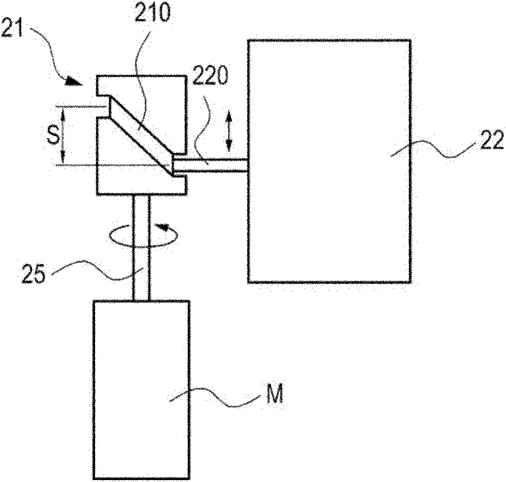
[0026] figure 2 is a schematic diagram showing a focus control device of a beam projector used in a portable terminal according to an embodiment of the present invention.

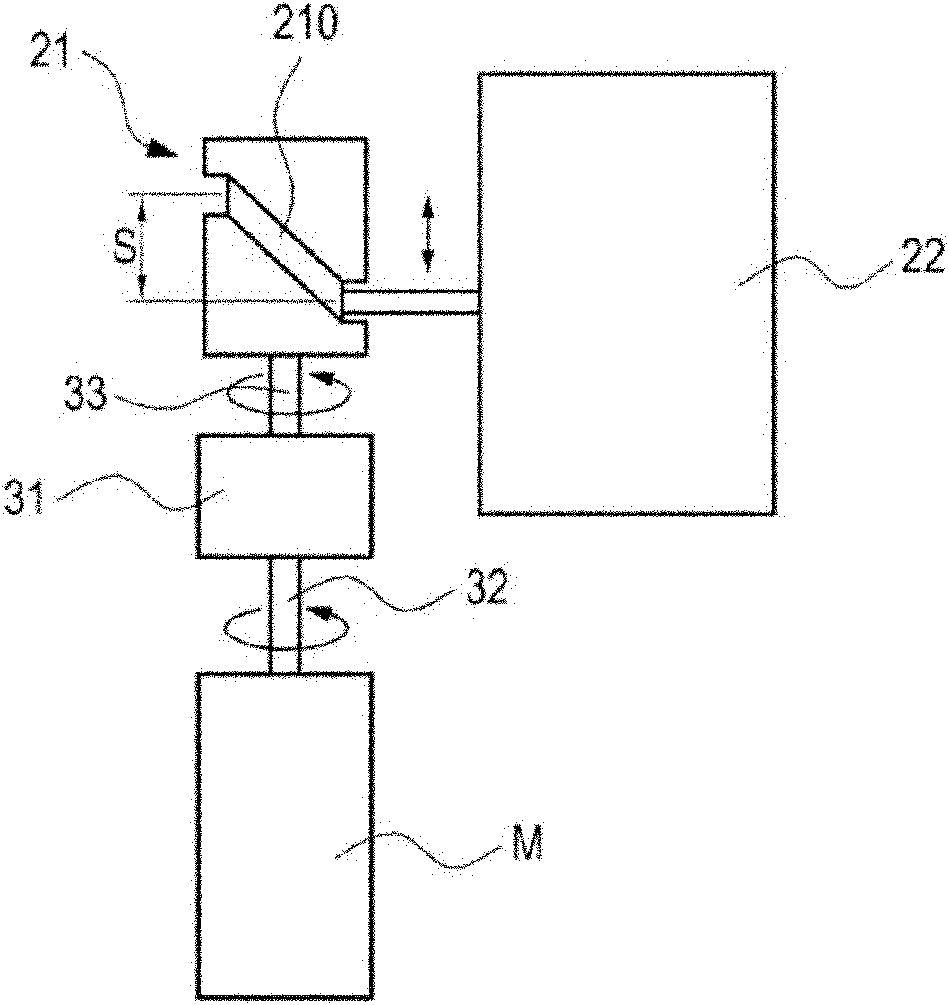
[0027] refer to figure 2 , The focus control device includes a drive motor M, a cam 21 and a projection lens barrel 22 . The driving motor M and the cam 21 are connected to eac...


PUM


Abstract

The invention provides a focus controlling device of a beam projector for use in a portable terminal. The focus controlling device includes a drive motor, a cam including a helical groove on an outer circumferential surface thereof, connected to the drive motor, and a projection lens barrel including a shaft that interworks with the helical groove to control focus by linearly sliding according to revolution of the cam.

Description

technical field [0001] The present invention relates generally to a small-beam projector used in a portable terminal, and more particularly, to a focus control device for the small-beam projector included in a portable terminal. Background technique [0002] The term "beam projector" generally refers to a device that realizes an image on a display device, transmits light generated by an additional light source into the display device, and projects the transmitted light onto a screen to provide an image. The focus of light transmitted through the display device can be adjusted based on the distance of the lens from the screen. [0003] Such a beam projector can easily control the image size. However, as the image is enlarged, the image quality deteriorates and colors are not accurately depicted in some lighted areas. Some of these disadvantages have been overcome by recent technologies for manufacturing display devices and lens systems. [0004] In addition, since a beam p...

Claims


Application Information

Patent Timeline
Patent Type & Authority Applications(China)
IPC IPC(8): G03B21/53H04N5/74
CPCG02B13/001G03B21/14G03B17/14G02B7/08G03B21/53G03B3/02G03B21/142
Inventor 朴重完
Owner SAMSUNG ELECTRONICS CO LTD
Learn More