Capacitor shaping, detecting and conveying mechanism
A technology for conveying mechanisms and capacitors, applied in capacitors, capacitor manufacturing, instruments, etc., can solve problems such as elastic fatigue, poor reliability, and many working steps, and achieve the effects of improving mechanization level, overcoming time-consuming and labor-intensive, and simplifying mechanical structures
- Summary
- Abstract
- Description
- Claims
- Application Information
AI Technical Summary
Problems solved by technology
Method used
Image

Examples
Embodiment 1
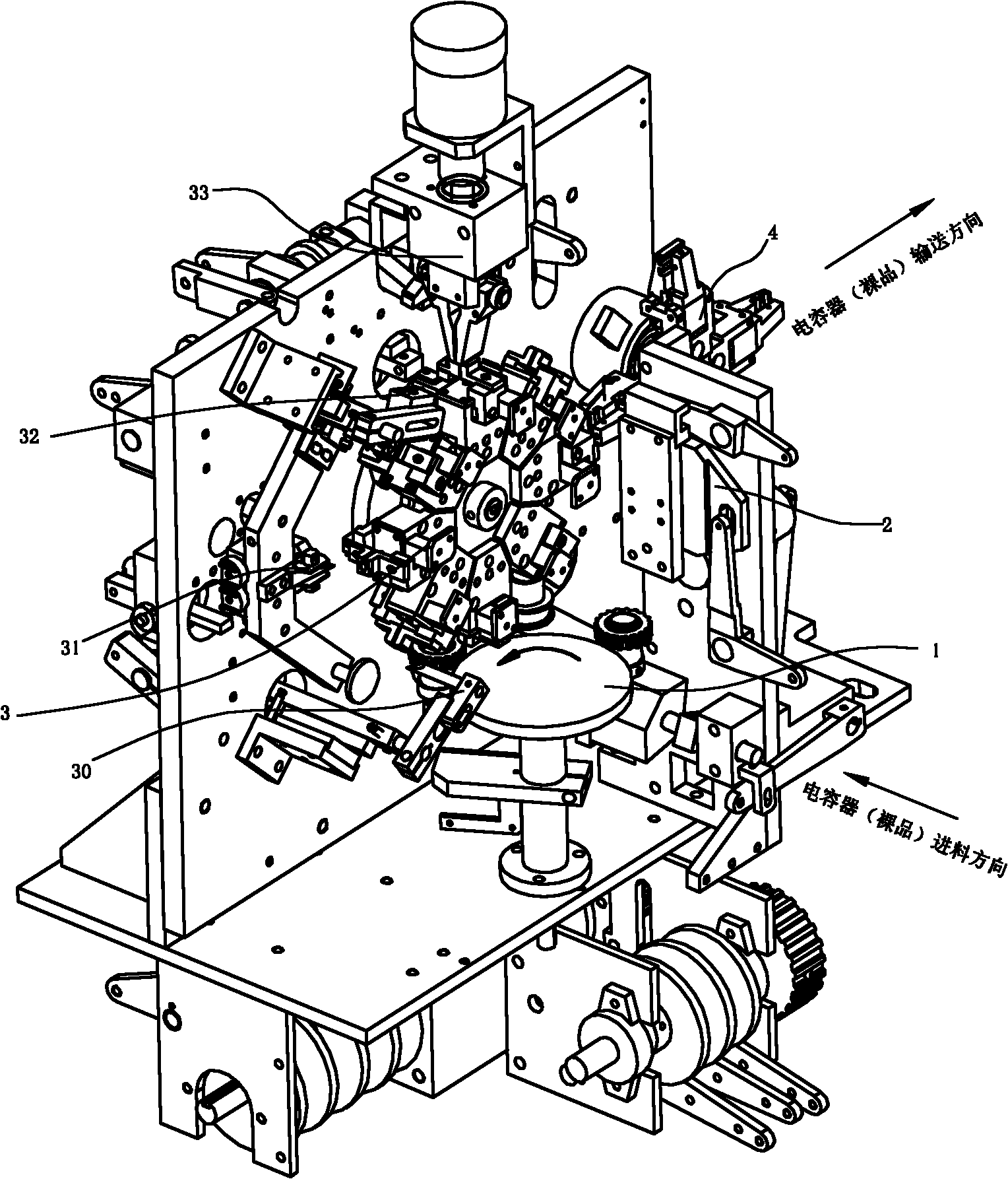
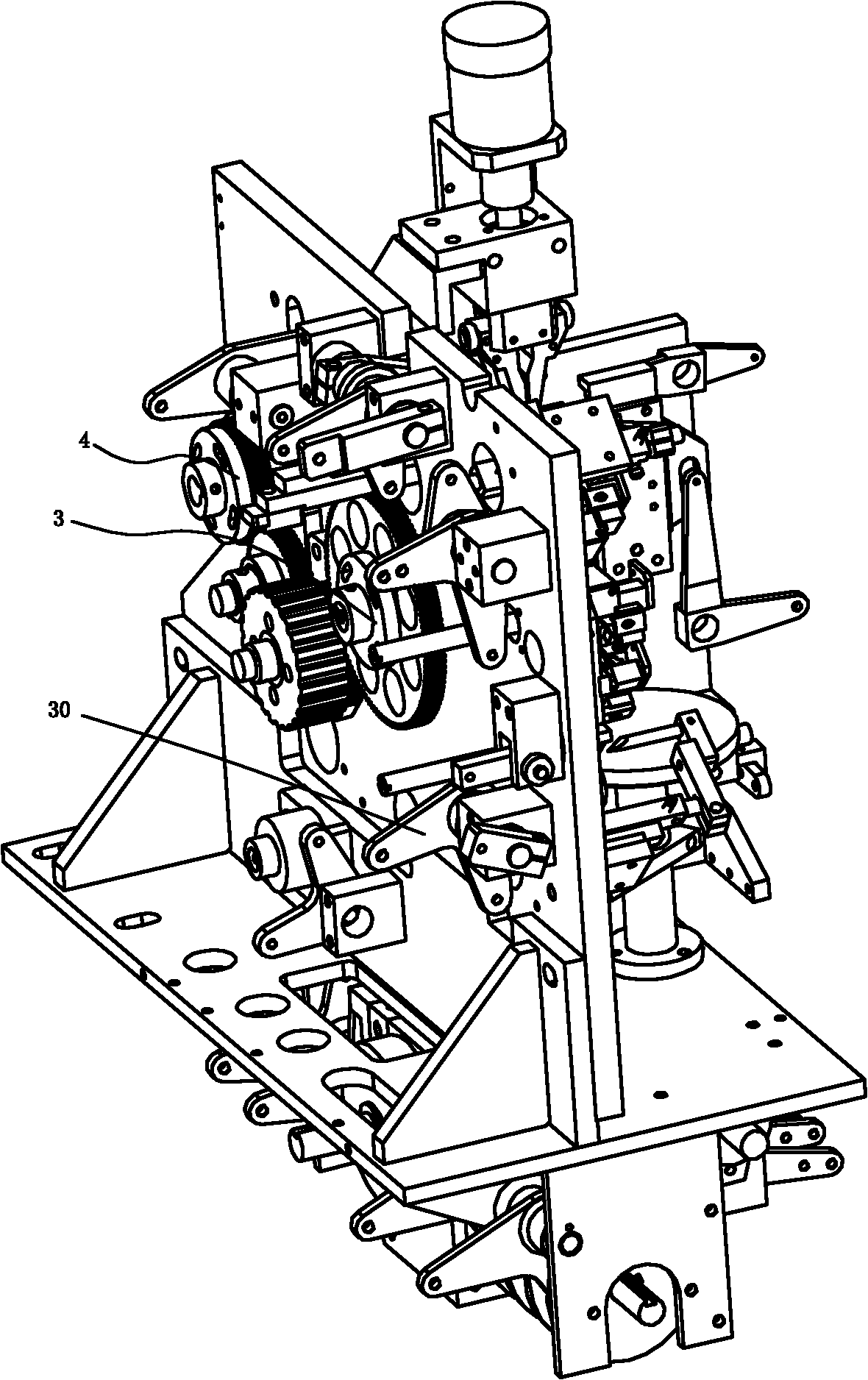
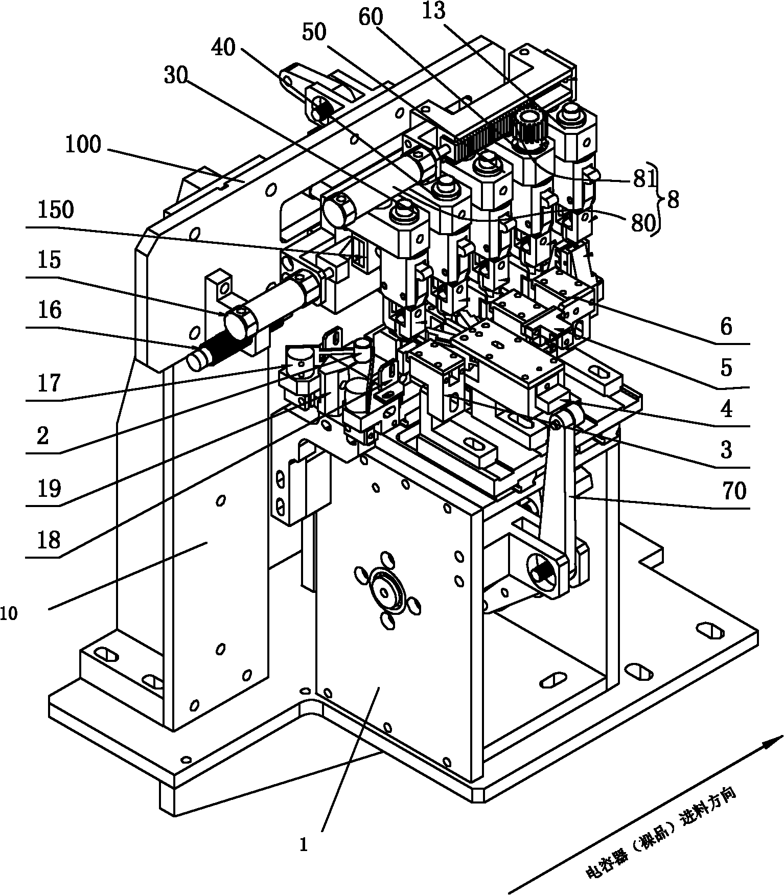
[0023] Such as Figure 3 to Figure 7 As shown, this embodiment provides a capacitor shaping detection and conveying mechanism, which includes a base 1 and an upper support plate 10 fixed on the base 1. A pair of capacitors 2 passing along a straight line are provided on the same horizontal position of the base 1. The foot opening device 3, the whole foot device 4, the polarity detection device 5 and the polarity reversing device 6 for opening feet, whole feet, polarity detection and polarity reversal in sequence, the base 1 is provided with a control switch The cam mechanism 7 operated by the foot device 3, the foot setting device 4, the polarity detection device 5, and the polarity reversing device 6.
[0024] Continue as image 3 , Figure 5 to Figure 7 As shown, the base 1 is symmetrically provided with a front slide rail plate 11 and a rear slide rail plate 12 that can slide toward or away from each other on the base 1 under the capacitor; the leg opening device 3 includes a ...
Embodiment 2
[0033] Such as image 3 , Image 6 with Figure 7 As shown, the only difference from the first embodiment is that when the delivered capacitor needs to be placed horizontally, a lateral flip device 20 that can rotate the capacitor underneath by 90° is provided directly under the upper feeding clamp 13 The device is provided with a flipping clamp 200, and a rotating driving wheel arm 201 and an opening and closing driving arm 202 that drive the flipping clamp 200 to rotate and open and close respectively. The capacitor is horizontally rotated by 90° through the horizontal flipping device 20 and then sent out.
Embodiment 2
[0034] In combination with the second embodiment, the working principle of the present invention is briefly described:
[0035] When the capacitors at other stations are transferred to the detection conveying mechanism, the infrared sensor 18 on the feed port side of the front slide rail plate 11 and the rear slide rail plate 12 first senses whether there is a capacitor at the feed port, and then The capacitor on the horizontal feeding fixed block 19 is opened through the baffle clip group 17 and sent into the feeding port. At this time, the transfer cam device 14 on the rear side of the upper support plate 10 drives the first upper side of the transfer plate 100 The conveying clamp 30, the second upper conveying clamp 40, the third upper conveying clamp 50, the fourth upper conveying reversing clamp 60 and the upper feeding clamp 13 are opened together and moved to the left, the first upper conveying clamp 30 First, the capacitor is clamped, and the second upper conveying clamp ...
PUM
 Abstract
Description
Claims
Application Information
 - R&D
- Intellectual Property
- Life Sciences
- Materials
- Tech Scout
- Unparalleled Data Quality
- Higher Quality Content
- 60% Fewer Hallucinations
Browse by: Latest US Patents, China's latest patents, Technical Efficacy Thesaurus, Application Domain, Technology Topic, Popular Technical Reports.
© 2025 PatSnap. All rights reserved.Legal|Privacy policy|Modern Slavery Act Transparency Statement|Sitemap|About US| Contact US: help@patsnap.com