
Mold used for forming casting bar, casting device, and method for producing casting bar

一种铸棒、铸模的技术,应用在铸棒形成用铸模、铸造装置和铸棒的制造领域,能够解决不适用等问题,达到制造效率和成品率提高、提高制造效率、降低制造成本的效果

Inactive Publication Date: 2011-07-20
PANASONIC CORP
View PDF11 Cites 8 Cited by
  • Summary
  • Abstract
  • Description
  • Claims
  • Application Information

AI Technical Summary

Problems solved by technology

Such a casting mold for continuous casting is not suitable for the production of cast rods having a long length relative to the width (diameter) as described above.

Method used


Image

  • Mold used for forming casting bar, casting device, and method for producing casting bar
  • Mold used for forming casting bar, casting device, and method for producing casting bar
  • Mold used for forming casting bar, casting device, and method for producing casting bar

Examples


Embodiment Construction

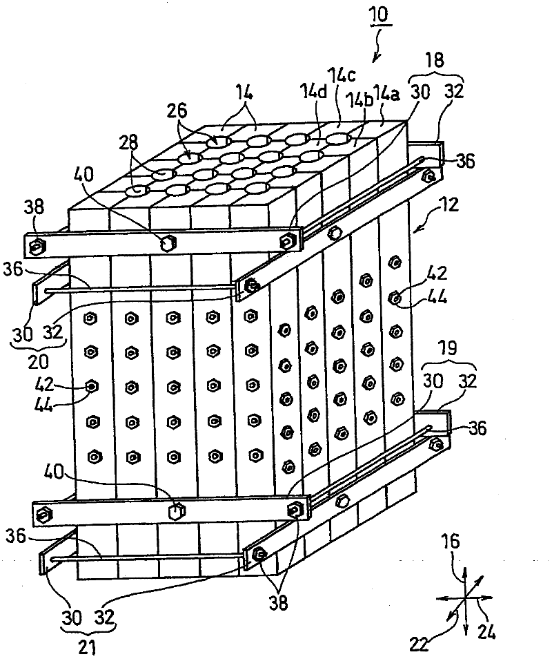
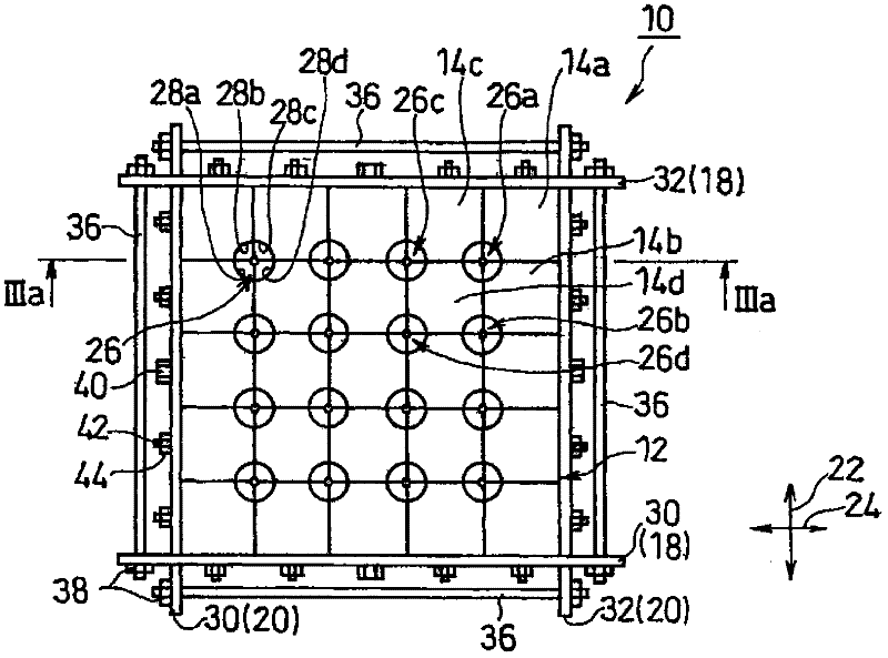
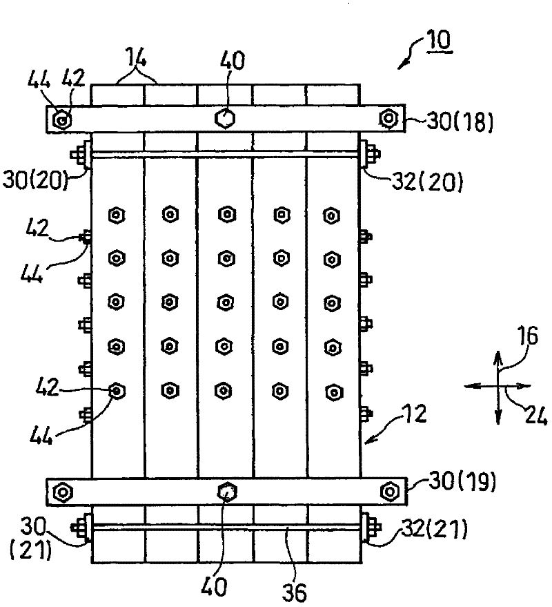
[0048] figure 1It is a perspective view which shows one Embodiment of the casting mold for casting rods of this invention. Figure 2A yes figure 1 top view of Figure 2B yes figure 1 main view of Figure 2C yes figure 1 right side view of the , Figure 2D yes figure 1 bottom view. Figure 3A yes Figure 2A and Figure 2C IIIa-IIIa arrow direction view, Figure 3B yes Figure 3A A partial enlargement of the . in addition, Figure 4 is the composition figure 1 A plan view of the modules of the shown module assembly separated from each other in a direction perpendicular to the longitudinal direction.

[0049] In addition, in the description of the following casting molds for casting rods and casting equipment, when referring to directions, they are based on the directions when they are placed in the horizontal direction. Specifically, the direction arrows shown in each figure are benchmark.

[0050] refer to figure 1 and Figure 2A ~ Figure 2D , the casting mold...


PUM

PropertyMeasurementUnit
diameteraaaaaaaaaa

Abstract

Provided is a mold used for forming a casting bar which can be used repeatedly and can enhance the production efficiency or yield of a casting bar that expands at the time of solidification. Also provided is a casting device using the mold for forming a casting bar, and a method for producing the casting bar efficiently. The mold (10) used for forming a casting bar is equipped with a segment assembly (12) having a plurality of segments (14) arranged in parallel and a plurality of cavities (26) extending in the longitudinal direction (16), and means (18-21) for clamping the segment assembly (12) in the direction perpendicular to the longitudinal direction (16). Each of the plurality of segments (14) of the mold (10) has one or more cavity forming portions (28) which form a part of the circumferential surface of the cavities (26), wherein the cavity (26) is formed of a combination of two or more segments (14), and at least one of the plurality of segments (14) has two or more cavity forming portions (28).

Description

technical field [0001] The present invention relates to a casting mold and a casting device for producing cast rods and a method for producing cast rods. Background technique [0002] In recent years, thin film formation techniques have been widely adopted in the manufacture of various devices. For example, in solar cells and lithium-ion batteries, attempts have been made to use thin films of silicon. The use of such a thin film is important not only from the viewpoint of high performance and miniaturization of devices but also from the viewpoint of conservation of the global environment such as resource conservation and reduction of power consumption. Therefore, improvement in productivity and stability of thin film formation, and cost reduction are required. [0003] The improvement of the productivity of a thin film requires a long-term continuous film-forming technique, and vacuum deposition requires a continuous supply of a thin-film forming material to an evaporation...

Claims


Application Information

Patent Timeline
Patent Type & Authority Applications(China)
IPC IPC(8): B22C9/06B22C9/20C01B33/02
CPCB22C9/22C01B33/02B22C9/061
Inventor 本田和义神山游马篠川泰治
Owner PANASONIC CORP
Learn More