Swinging wire speed reducing device of wire winder

A cycloid deceleration and reel technology, which is applied in the transmission device, cable installation, cable arrangement between relative moving parts, etc. question

Inactive Publication Date: 2011-07-27
LG ELECTRONICS (TIANJIN) APPLIANCES CO LTD
View PDF3 Cites 1 Cited by
  • Summary
  • Abstract
  • Description
  • Claims
  • Application Information

AI Technical Summary

Problems solved by technology

[0004] The above-mentioned existing wire reel structures all have the problem of excessively fast wire return speed to varying degrees, which easily causes the wire to fly away from the wire reel, resulting in the occurrence of non-returning wires.
The main reasons are: 1) The spee

Method used


Image

  • Swinging wire speed reducing device of wire winder
  • Swinging wire speed reducing device of wire winder
  • Swinging wire speed reducing device of wire winder

Examples


Embodiment Construction

[0017] In order to further understand the invention content, characteristics and effects of the present invention, the following examples are given, and detailed descriptions are as follows in conjunction with the accompanying drawings:

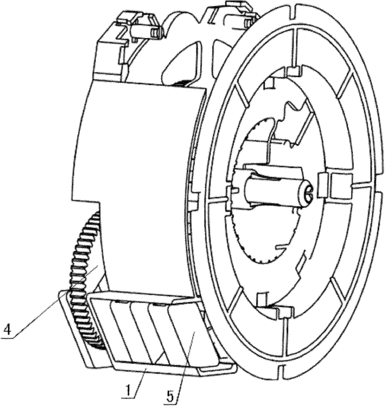
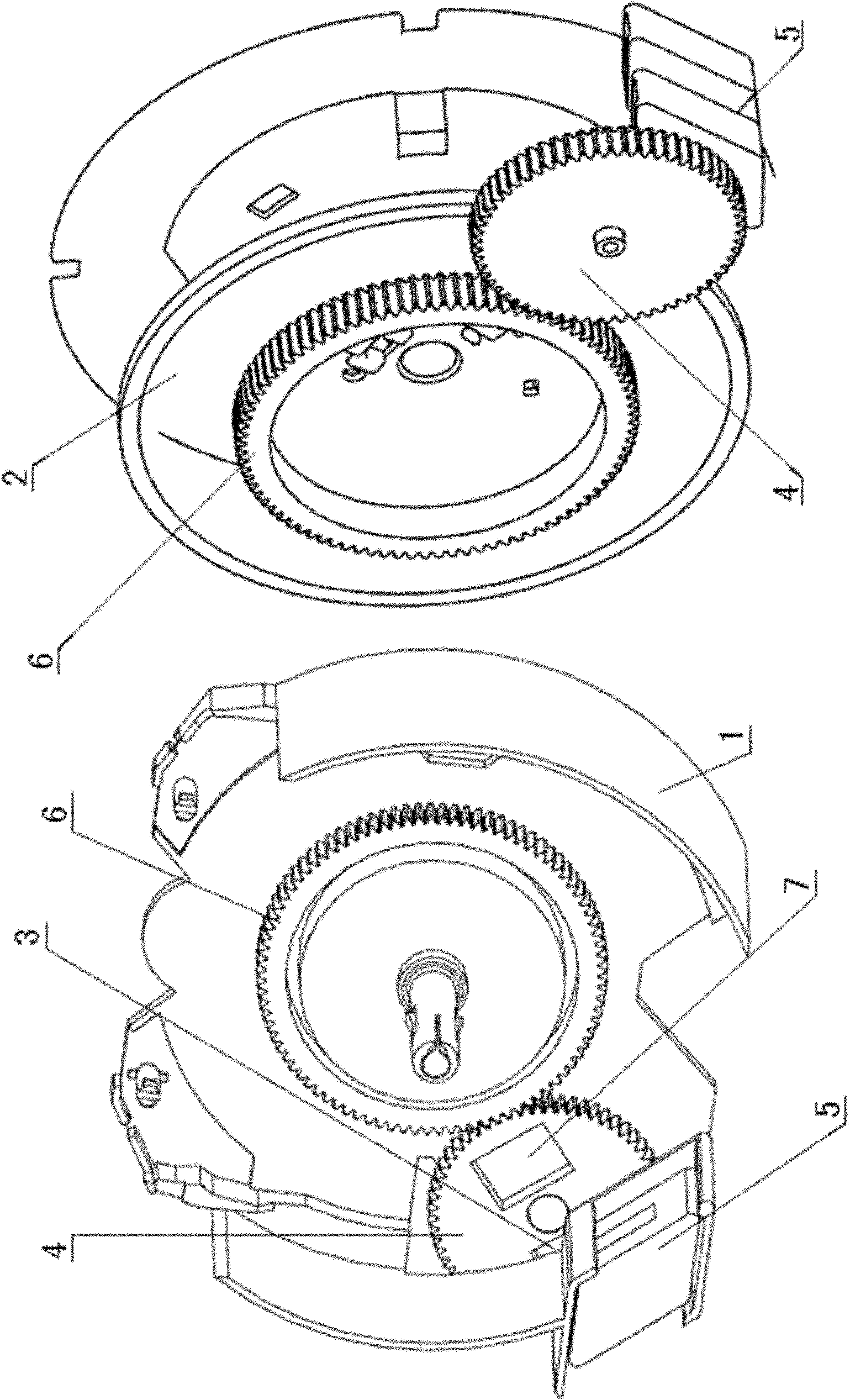
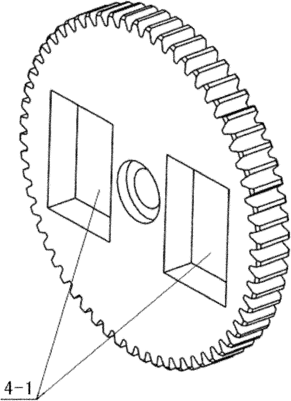
[0018] See Figure 1 ~ Figure 4 , a cycloid deceleration device for a reel, the reel includes a bracket 1 and a reel 2 mounted on the bracket 1, the device includes a cycloid block 5 slidably connected to the bracket 1, and the same as the reel 2 The transmission gear 6 fixed to the shaft and the rotating cycloid gear 4 meshed with the transmission gear 6, the rotating cycloid gear 4 is installed on the bracket 1, and is adjacent to the cycloid block 5, and the rotating cycloid gear 4 is on the pericycloid The block side is provided with two magnet placement grooves 4-1, and magnets 3 and 7 are respectively embedded in the two magnet placement grooves 4-1, and the magnets 3 and 7 are respectively placed on both sides of the center of the rota...


PUM


Abstract

The invention relates to a swinging wire speed reducing device of a wire winder. The wire winder comprises a bracket and a wire winding wheel arranged on the bracket; the device comprises a swinging wire block connected on the bracket in a sliding manner, and a transmission mechanism driven by the wire winding wheel. In the swinging wire speed reducing device, leftward and rightward wire swinging in the wire return process is realized, so that the condition that the wires are overlapped into a row to cause no wire return is avoided; and simultaneously, by mutual action between magnetic blocks, the energy is consumed, and the wire return speed is reduced, so that the condition that the wires fly away from the wire winder to cause no wire return is avoided.

Description

technical field [0001] The invention relates to a cycloid deceleration device, in particular to a cycloid deceleration device for a reel. Background technique [0002] Vacuum cleaner is a new type of advanced dust removal device. It is widely used in hotels, hospitals, gardens, shops, libraries, laboratories, computer rooms, homes, etc., with different specifications of suction heads, which can be used to clean carpets, It is very convenient to use for dust on clothes, sofas, household electrical appliances and electronic instruments. [0003] Now the power cord of the horizontal vacuum cleaner has an automatic return device. On November 3, 2010, Chinese patent application CN200910068670.6 disclosed a cord reel for a vacuum cleaner, including a reel with a combination of left and right reels and a reel shaft in the middle; The coil spring box of the coil spring; the wheel bracket on the left side of the reel; the reel button is also set on the wheel bracket; the plug limit...

Claims


Application Information

Patent Timeline
IPC IPC(8): B65H75/48F16H37/12B65H75/42A47L9/26
Inventor 徐昕皓洪明
Owner LG ELECTRONICS (TIANJIN) APPLIANCES CO LTD
Why Eureka
Try Eureka