
Energy-gathered charging structure for assisting in sampling of foreign planet minerals

A technology for shaped charge and minerals, applied in sampling devices, weapon accessories, blasting tubes, etc., can solve problems such as unfavorable collection and sampling work, scattering of mineral fragments, etc., and achieve the effects of small incidental damage, good safety, and small load.

Active Publication Date: 2021-01-19
BEIJING INSTITUTE OF TECHNOLOGYGY
View PDF8 Cites 1 Cited by
  • Summary
  • Abstract
  • Description
  • Claims
  • Application Information

AI Technical Summary

Problems solved by technology

The ordinary axial energy-shaping charge structure can use the energy-gathering effect to break and open solid minerals under the condition of small doses, and has less impact on the surrounding environment and potential safety hazards, but at the same time it will cause mineral fragments to fly around, which is not conducive to follow-up Collecting and sampling work, so it is necessary to redesign the special shaped charge structure to assist in the sampling of minerals on the surface of the alien planet

Method used


Image

  • Energy-gathered charging structure for assisting in sampling of foreign planet minerals
  • Energy-gathered charging structure for assisting in sampling of foreign planet minerals
  • Energy-gathered charging structure for assisting in sampling of foreign planet minerals

Examples


Embodiment Construction

[0030] The present invention will be described in detail below with reference to the accompanying drawings and examples.

[0031] This embodiment provides a shaped charge structure for assisting in the sampling of extraterrestrial minerals, which can be driven by less explosive explosions in a low-gravity, vacuum-free and oxygen-free environment to form an annular jet to penetrate hard minerals, and at the same time, drive flyers Breaking up bulk minerals facilitates sampling.

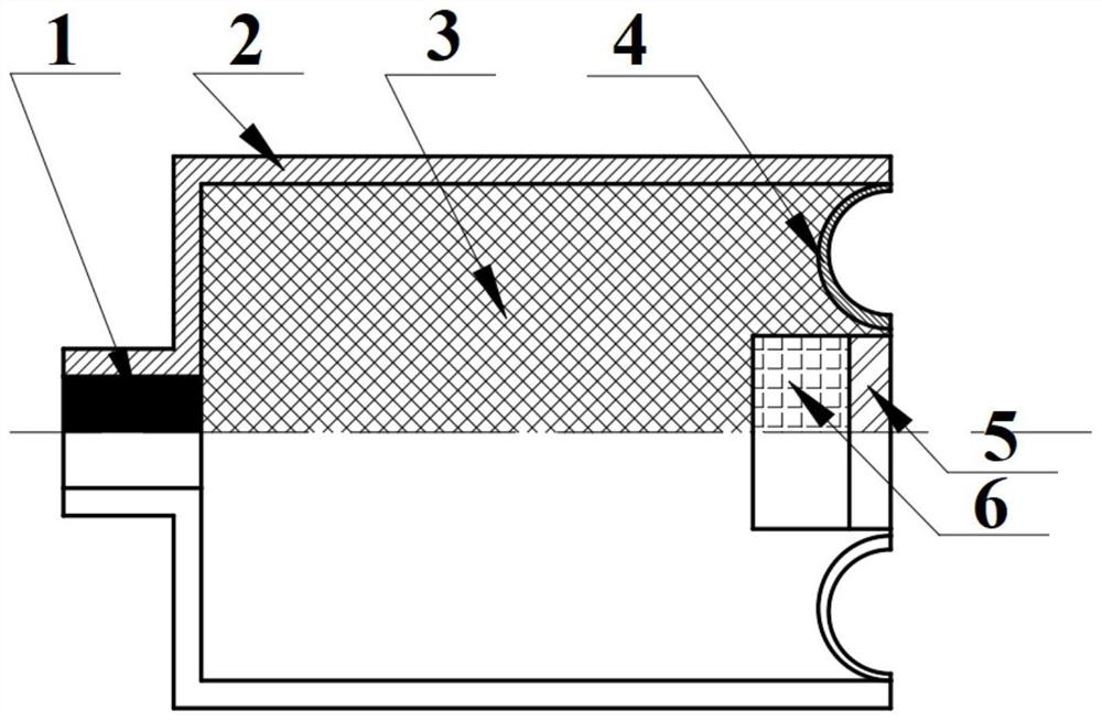
[0032] Such as figure 1 As shown, the shaped charge structure includes: an initiation mechanism 1 , a casing 2 , an explosive column 3 , an annular charge cover 4 , flyers 5 and a buffer body 6 .

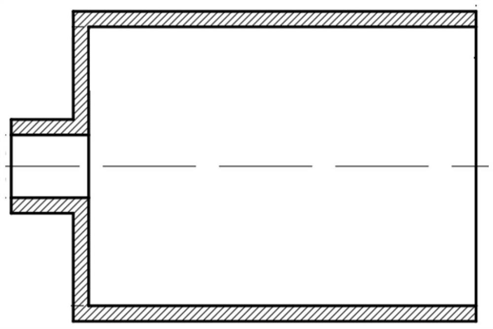
[0033] The connection relationship of the shaped charge structure is as follows: figure 2 As shown, the casing 2 is a stepped shaft-shaped circular tube with openings at both ends, and the explosive column 3 is coaxially filled in the inner cavity of the large end of the casing 2, so that one end of the e...


PUM


Abstract

The invention discloses an energy-gathered charging structure for assisting in sampling of foreign planet minerals. The energy-gathered charging structure comprises a detonating mechanism, a shell, anexplosive column, an annular shaped charge liner, a flying sheet and a buffer body, wherein the shell is a stepped shaft-shaped circular tube, the two ends of the shell are separately opened, the explosive column is coaxially filled in an inner cavity at the large end of the shell, one end of the explosive column is propped against the inner bottom surface of the shell, the other end of the explosive column is in compression fit with the end part of the shell through the annular shaped charge liner, and the convex surface of the annular shaped charge liner is compressed at the end part of theexplosive column; the flying sheet is arranged between the central end surface of the annular shaped charge liner and the explosive column, and the buffer body is arranged between the flying sheet and the explosive column; the detonating mechanism is arranged in the small end of the shell and used for detonating the explosive column; and the annular shaped charge liner comprises an annular grooveand a circular end face integrally connected to the center of the annular groove, the cross section of the annular groove is in a crescent shape, the end, connected with the circular end face, of theannular groove is the inner side, the end, connected with the shell, of the annular groove is the outer side, and the wall thickness of the inner side of the annular groove is larger than that of theouter side of the annular groove.

Description

technical field [0001] The invention relates to the technical field of engineering blasting and extraterrestrial mineral sampling, in particular to an energy-gathering charge structure for assisting extraterrestrial mineral sampling, and in particular to a method for crushing solid minerals on an extraterrestrial planet by utilizing explosive column explosion, energy-gathering, and crushing effects. A shaped charge structure for collecting effective small samples. Background technique [0002] Mineral sampling usually carried out on the surface of the earth refers to taking a certain amount of mineral samples from ore bodies, mines, etc. according to certain specifications or weight requirements, and conducting mineralogy, mineralogy and petrology on ores and rocks through analysis, testing and identification. The research is to ascertain the mineral composition and content of ore and surrounding rock, symbiotic combination, structural structure, mineral particle size and em...

Claims


Application Information

Patent Timeline
IPC IPC(8): F42B3/00F42B3/10G01N1/08
CPCF42B3/00F42B3/10G01N1/08
Inventor 蒋建伟彭嘉诚门建兵王树有李梅
Owner BEIJING INSTITUTE OF TECHNOLOGYGY
Learn More