

Loopback detection device and method
A loopback detection and port technology, applied in the field of communication, can solve the problems of low reliability and high cost, and achieve the effect of high reliability and low cost
- Summary
- Abstract
- Description
- Claims
- Application Information
AI Technical Summary
Problems solved by technology
Method used
Image

Examples
Embodiment 1
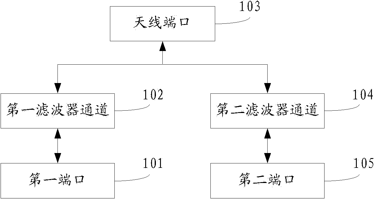
[0030] This embodiment provides a loopback detection device, see figure 1 , the device consists of:
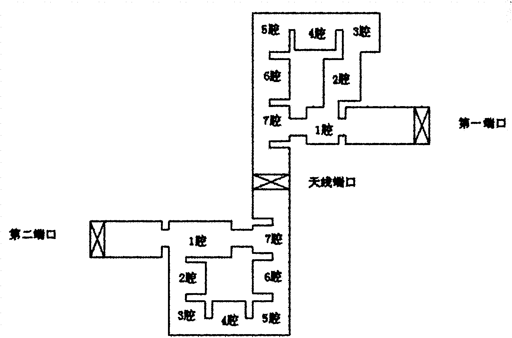
[0031] The first port 101, the first filter channel 102, the antenna port 103, the second filter channel 104, and the second port 105 connected in sequence; the first filter channel 102 includes a first resonant cavity and a second resonant cavity, the There are at least three resonant cavities between the first resonant cavity and the second resonant cavity, and there is a coupling hole between the first resonant cavity and the second resonant cavity.
[0032] Optionally, the second filter channel 104 includes a third resonant cavity and a fourth resonant cavity, at least three resonant cavities are included between the third resonant cavity and the fourth resonant cavity, and the third resonant cavity and the fourth resonant cavity There is a coupling hole between them.
[0033] Correspondingly, the first port 101 is a transmitting port, and the second port 105 is a receiv...
Embodiment 2
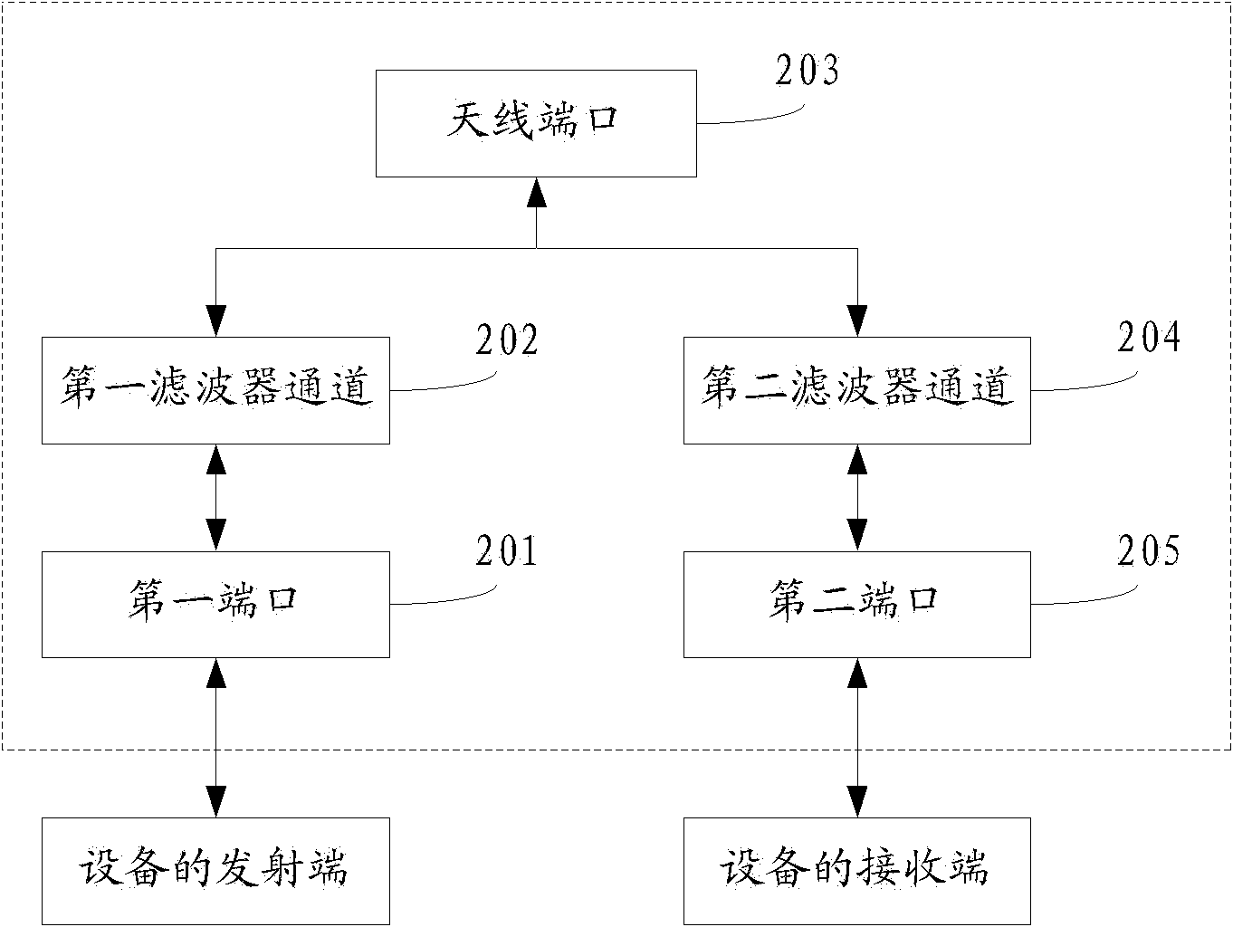
[0045] This embodiment provides a loopback detection device, which is different from the prior art. In the prior art, a coupling hole is opened between the two filter channels of the duplexer, and structures and devices such as a circulator and a load are added according to the principle of a four-port coupler to realize the loopback detection function, and the signal of the loopback detection is avoided. Open the filter at the transmitting end, send from the coupling hole to the filter at the receiving end, and then reach the receiving end. However, the loopback detection device provided by the present invention does not need to add other devices, and adopts the mode of opening a coupling hole between the resonant cavities of the filter channel to change the performance of the filter, so that the received frequency band signal of the opposite port can pass through the filter. , so as to achieve loopback detection. A loopback detection system such as figure 2 as shown, fi...
Embodiment 3
[0063] see Figure 7 , this embodiment provides a loopback detection method, which is implemented by using the loopback detection devices in the first and second embodiments above, which is different from the prior art. In the prior art, the loopback detection signal avoids the filter at the transmitting end, is sent to the filter at the receiving end through the coupling hole opened between the two filter channels of the duplexer, and then reaches the receiving end. However, the method provided by the present invention changes the performance of the filter by opening a coupling hole between the resonant cavities of the filter channel, so that the received frequency band signal of the opposite port can pass through the filter, thereby realizing loopback detection. The method flow is as follows:
[0064] 701: Open a coupling hole between the first resonant cavity and the second resonant cavity of the first filter channel, including at least three resonant cavities between the ...
PUM
 Abstract
Description
Claims
Application Information