Ultrasound probe and ultrasound diagnostic apparatus

An ultrasonic and echo technology, applied in the field of ultrasonic probes, can solve the problems of amplification of weak signal components that cannot be SCW, and the inability to reduce signal lines, so as to ensure the receiving performance and reduce the number of wires.

Active Publication Date: 2011-08-03
TOSHIBA MEDICAL SYST CORP
View PDF4 Cites 17 Cited by
  • Summary
  • Abstract
  • Description
  • Claims
  • Application Information

AI Technical Summary

Problems solved by technology

[0020] Therefore, the conventional ultrasonic probe with a built-in receiving beamformer cannot faithfully amplify the weak signal components of SCW due to the constraints of the above-mentioned beamformer. The vibrator adds the output signal and outputs it to the body of the ultrasonic diagnostic device
Therefore, conventional ultrasonic probes cannot reduce the number of signal lines in the probe cable connecting the ultrasonic probe and the ultrasonic diagnostic device body, and the probe cable can only be thicker.

Method used


Image

  • Ultrasound probe and ultrasound diagnostic apparatus
  • Ultrasound probe and ultrasound diagnostic apparatus
  • Ultrasound probe and ultrasound diagnostic apparatus

Examples


no. 1 Embodiment approach

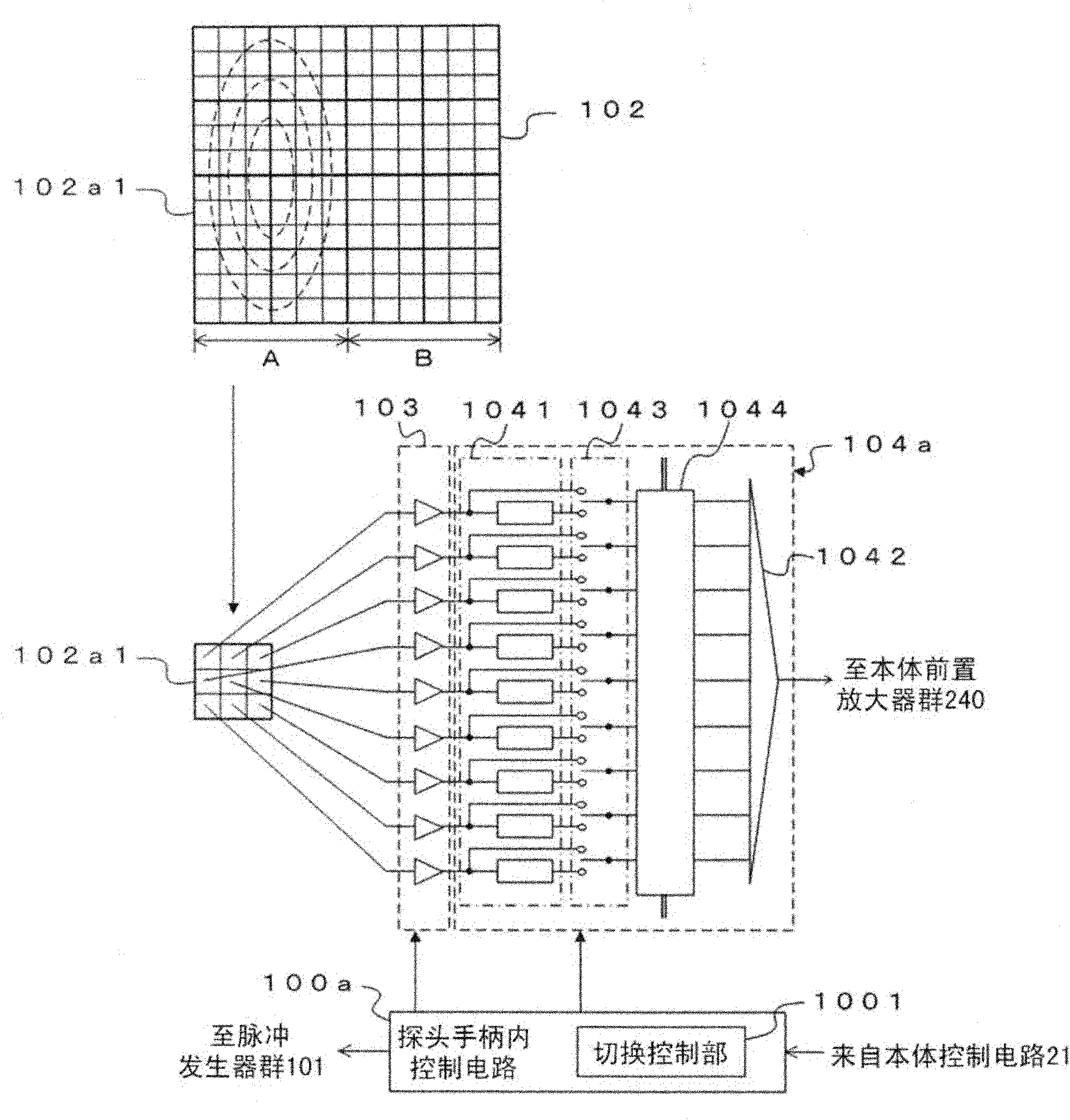
[0043] First, refer to figure 1 The configuration of the ultrasonic probe according to the first embodiment will be described. From the probe connector 12 to the structure of the ultrasonic diagnostic device body 2, and Figure 9 The configuration of the conventional ultrasonic diagnostic apparatus shown is the same, and here, the configuration of the ultrasonic probe 1 will be described in detail.

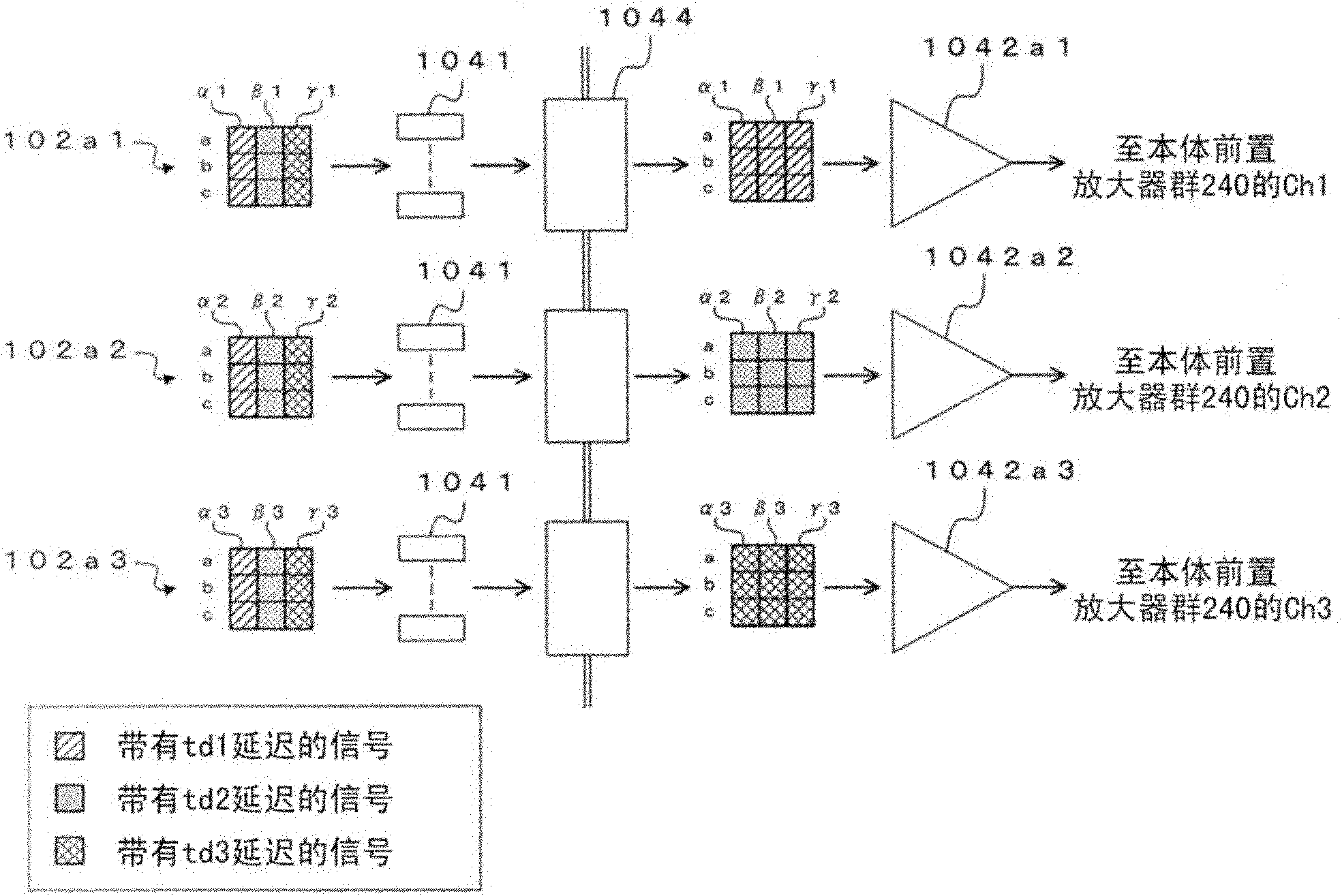
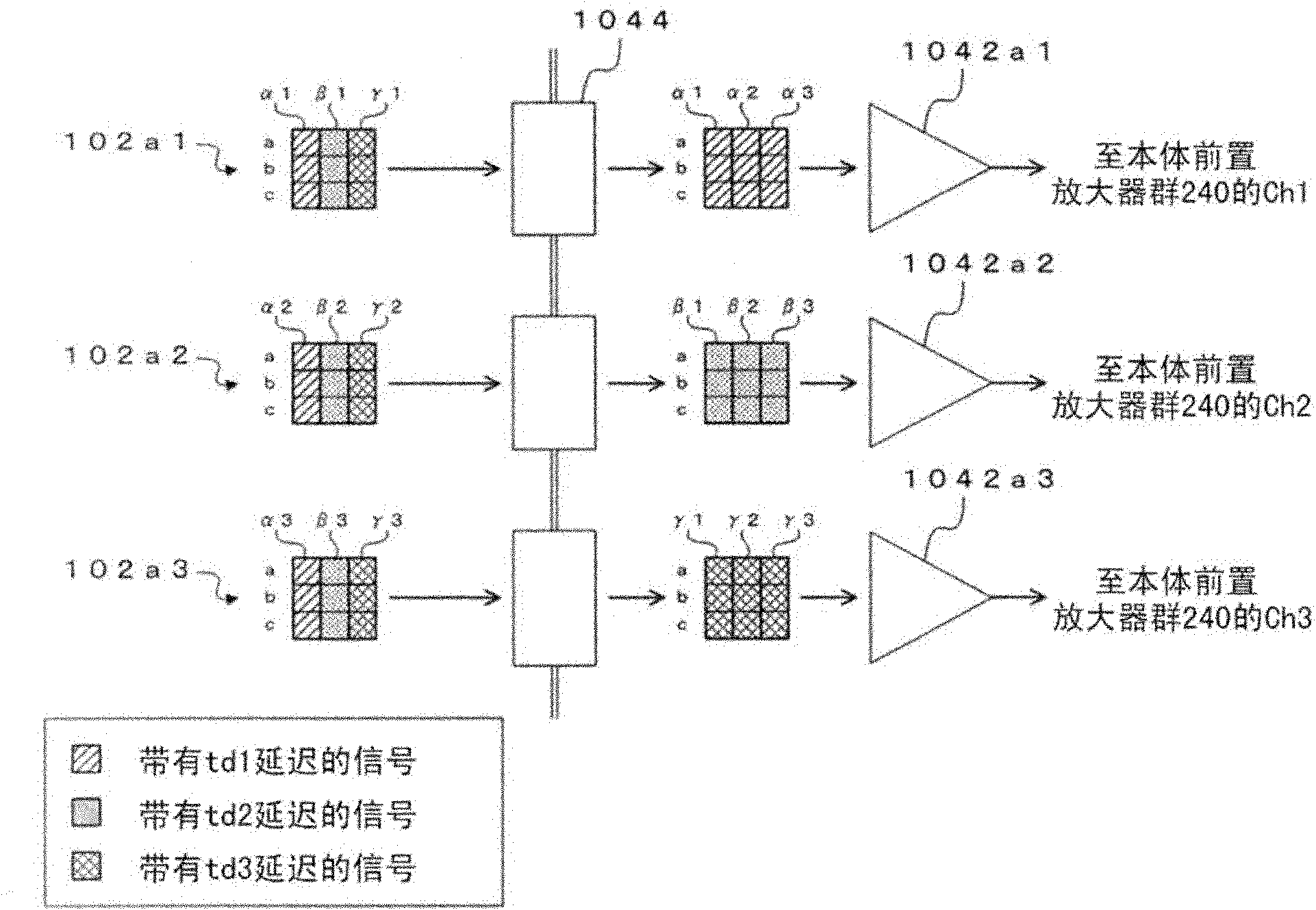
[0044] Such as figure 1 As shown, the channel control circuit 104a of this embodiment is characterized in that: in addition to the subarray receiving beamformer group 1041 and the adder 1042, it also includes a bypass switch (bypass switch) 1043 and a matrix switch (matrix switch) 1044. Therefore, in this description, attention will be paid to the structure in the probe handle 10 which is different from the structure of the conventional ultrasonic probe, the main body reception delay adding circuit 241 and the control device in the ultrasonic diagnostic apparatus main body 2 w...

Deformed example 2

[0120] Below with respect to the structure of the ultrasonic probe of modification 2, refer to Figure 6 Be explained. Figure 6 It is a block diagram of the channel control circuit 104c in the ultrasonic probe according to Modification 2. In addition, in the description of the ultrasonic probe according to Modification 2, attention will be paid to the configurations of the preamplifier group 103 and the bypass switch 1043 and the configurations of the switching control unit 1001 and The operation of the matrix switch 1044 in the first mode will be described (the operation in the second mode is the same as in the first embodiment).

[0121] In the ultrasonic probes according to the first embodiment and Modification 1, due to the structural reasons of the channel control circuits 104a and 104b, the phase types that can be set for the respective transducers in the region A receiving ultrasonic waves are received by input signals to the respective adders. The limit on the numbe...


PUM


Abstract

The present invention provides an ultrasound probe and an ultrasound diagnostic apparatus. The present embodiment relates to the ultrasound probe having a first ultrasound vibrator group and a second ultrasound vibrator group, comprising a plurality of matrix switches and an adder. The ultrasound probe has a mode to send ultrasound to a predetermined observation point within a subject by the first ultrasound vibrator group, and to receive ultrasound echoes reflected within the subject by the second ultrasound vibrator group. The plurality of matrix switches extract, based on the distance between the second ultrasound vibrator group and the observation point, a plurality of ultrasound echoes having substantially the same phase from a plurality of ultrasound echoes output by the second ultrasound vibrator group. The adder adds the plurality of ultrasound echoes extracted by the plurality of matrix switches for each of the matrix switches and outputs them.

Description

technical field [0001] This aspect relates to an ultrasonic probe that is connected to an ultrasonic diagnostic device and sends and receives ultrasonic waves to a subject, especially an ultrasonic probe that is not limited by circuit performance and can reduce the number of probe cable signal lines while ensuring a wide dynamic range. technology. Background technique [0002] In recent years, in ultrasonic two-dimensional (2D) array probes and the like, circuits are built into the head of the probe to perform generation of transmission waveforms, amplification of reception echoes (reception signals), and partial beamforming. An ultrasonic diagnostic apparatus using such an ultrasonic two-dimensional array probe is described in, for example, Japanese Patent Application Laid-Open No. 2007-167445. [0003] Usually, to the main body of the ultrasonic diagnostic apparatus to which such an ultrasonic probe is connected via a probe connector, the ultrasonic echo signals subjected...

Claims


Application Information

Patent Timeline
IPC IPC(8): A61B8/00
CPCG01S15/8927A61B8/54G01S7/5208G10K11/345G01S15/8979G01S7/52066A61B8/00G01S15/8915
Inventor 本乡宏信平野亨内海勋石塚正明椎名孝行
Owner TOSHIBA MEDICAL SYST CORP
Why Eureka
Try Eureka