
Hydraulic braking structure for aircraft with half-cavity brake

A hydraulic braking and semi-cavitation technology, which is applied in the direction of brakes, braking transmissions, braking safety systems, etc., can solve the problems of low sensitivity

Active Publication Date: 2011-08-03
SAFRAN LANDING SYSTEMS
View PDF4 Cites 0 Cited by
  • Summary
  • Abstract
  • Description
  • Claims
  • Application Information

AI Technical Summary

Problems solved by technology

[0017]Finally, such a structure exhibits low sensitivity to failure, assuming that most components are redundant: two independent brake circuits, each for two brake halves power supply (one for each braked wheel), each, although not optimal, is suitable for delivering a certain level of braking characteristics, assuming the brakes are controlled in pairs

Method used


Image

  • Hydraulic braking structure for aircraft with half-cavity brake
  • Hydraulic braking structure for aircraft with half-cavity brake
  • Hydraulic braking structure for aircraft with half-cavity brake

Examples


Embodiment Construction

[0032] Figure 5 is a schematic diagram showing a first specific embodiment of the invention applied to an aircraft with four braked wheels.

[0033] The reference numerals of those elements common to other structures are incremented by 100. In this example, each detent includes two half-cavities 102a and 102b.

[0034] The structure includes two hydraulic brake circuits N1 and N2, respectively supplying power to the semi-cavities 102a and 102b, and operating simultaneously.

[0035] The brake circuit N1 comprises four servo valves 103 each supplying power to only one of the half-cavities 102a. The brake circuit N2 comprises only two servo valves 104, each powering two of the half-cavities 102b. Thus, according to the invention, on each brake at least one semi-cavity is energized by a servo valve that supplies only said semi-cavity, so that wheel-to-wheel braking can be optimized. This configuration includes the parking circuit P associated with the same hydraulic power so...


PUM


Abstract

A hydraulic braking structure for aircraft comprises a plurality of wheels equipped with brakes (102; 202); each brake comprises two half cavities (102a, 102b; 202a, 202b); the structure comprises: a first braking circuit (N1) with servo valves (103; 203), wherein each servo valve supplies power to one or more half cavities on a single brake; and a second braking circuit (N2) with servo valves (104; 204), wherein each servo valve supplies power to one or more half cavities on a single brake; the two hydraulic circuits operate simultaneously in such a way that: on each brake, one of the half cavities is supplied by the servo valves of the first braking circuit, and the other half cavity is supplied by the servo valves of the second braking circuit, and at least one of the half cavities is supplied by the servo valve that only supplies power to the half cavity.

Description

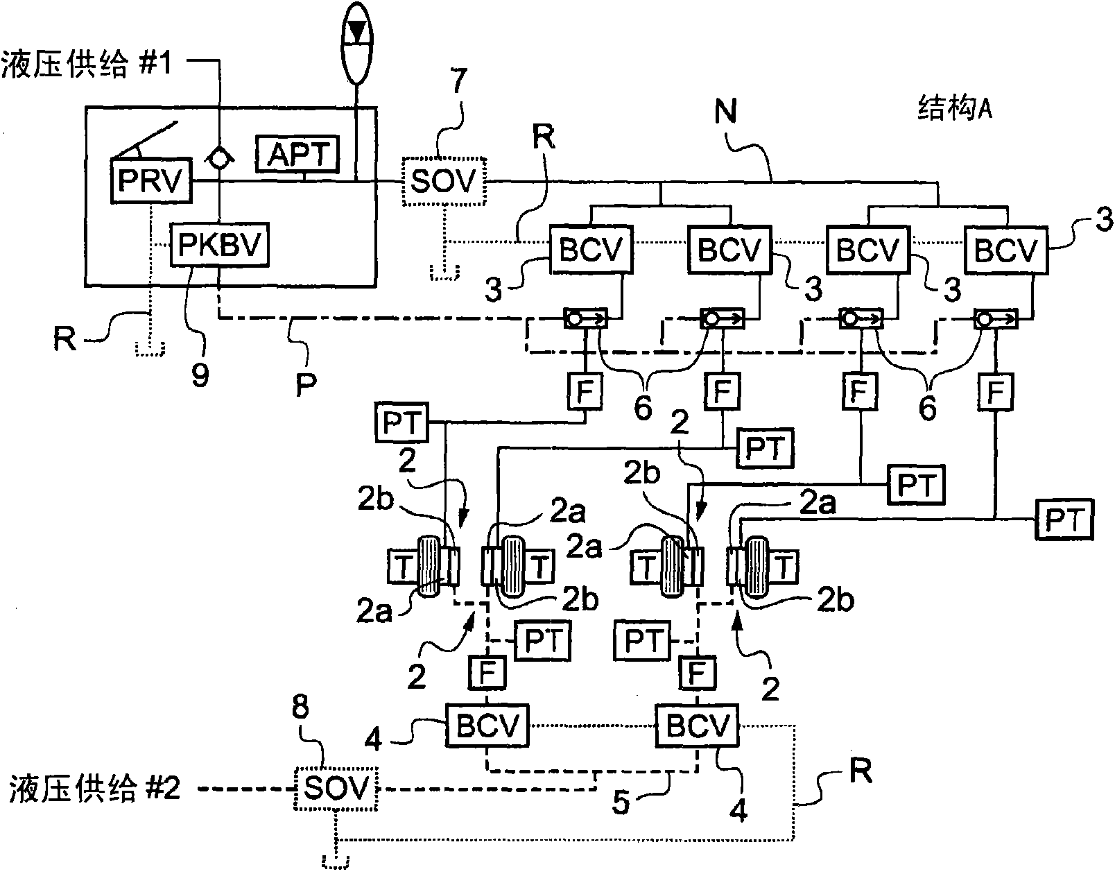
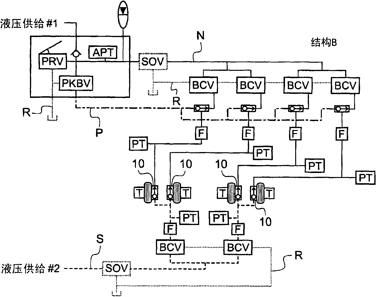
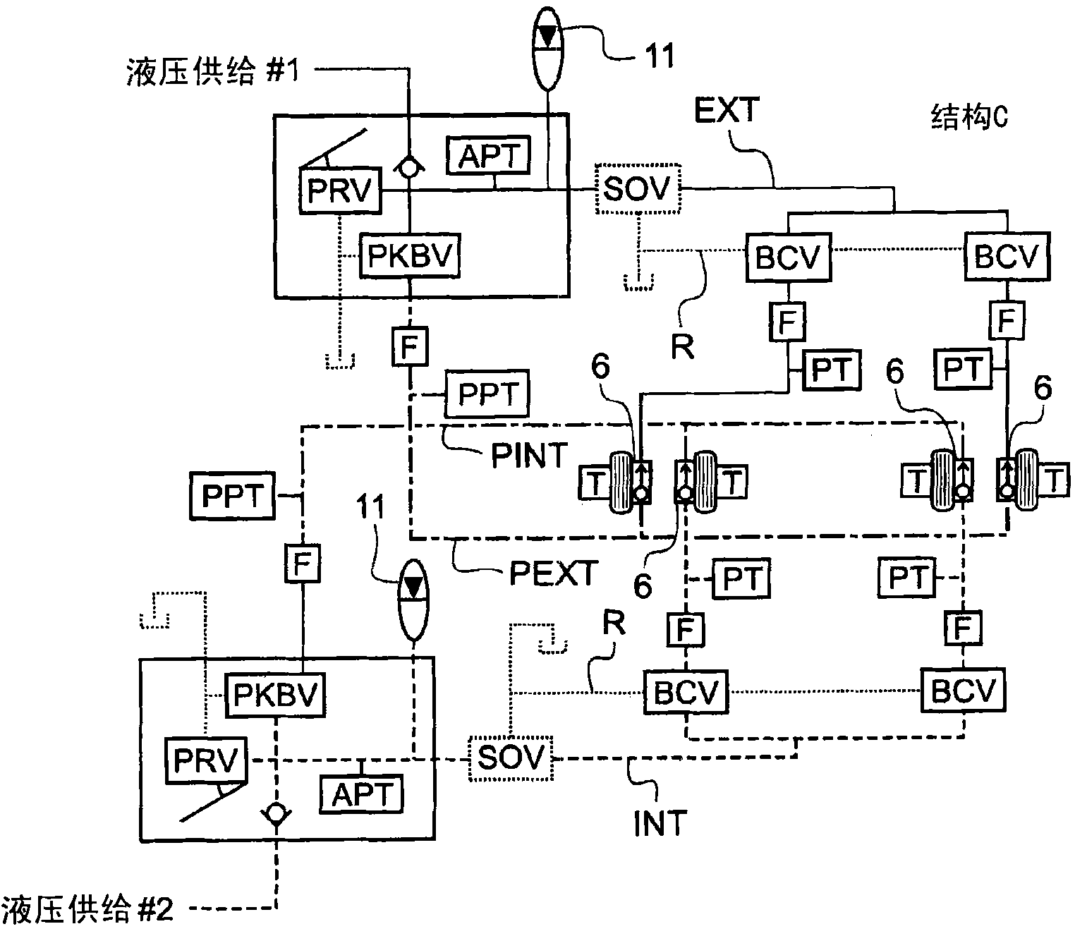
technical field [0001] The present invention relates to a hydraulic braking structure for aircraft having a semi-cavity brake. Background technique [0002] Various types of hydraulic braking structures are known, depending on whether the aircraft manufacturer seeks to increase the payload, performance, maintainability or availability of said structure. These different types of structures are schematically illustrated in the Figures 1 to 4 Medium, for aircraft with four braked wheels. [0003] show on figure 1 The first type of structure A in A includes two brake circuits, one of which is the normal circuit N (thick solid line) and the other is the emergency circuit S (thick dashed line). The four brakes 2 each comprise two cavities 2a and 2b, each of which is powered by only one of the brake circuits. The normal circuit N consists of four valves 3, in this example specifically servo valves or brake control valves (BCV), each valve supplying power to one of the cavities...

Claims


Application Information

Patent Timeline
IPC IPC(8): B60T13/68B60T13/74B64C25/42
CPCB60T8/00B60T8/325B60T13/686B60T17/18B60T8/345
Inventor D·弗兰克
Owner SAFRAN LANDING SYSTEMS
Learn More