Crank, crankshaft, combined crankshaft and internal combustion engine or compressor using combined crankshaft

A technology of combining crankshafts and cranks, applied in the field of internal combustion engines or compressors and cranks, can solve problems such as the influence of machine stability and reliability reduction

Active Publication Date: 2011-08-03
BEIJING SINOCEP ENGINE TECH
View PDF9 Cites 6 Cited by
  • Summary
  • Abstract
  • Description
  • Claims
  • Application Information

AI Technical Summary

Problems solved by technology

[0007] The crankshaft disclosed above is essentially a combined crankshaft, that is, the crankshaft is not integral, but is assembled from a single component, wherein the crank pin mounting holes on the crank that make up the crankshaft can be through holes or It can be a bulky hole (even if it is a bulky hole, a via hole for assembling bolts is also provided on the bottom wall of the bulky hole, and can refer to the attached Figure 2-2 ); Regardless of the crank pin installation hole position through hole or bulkhead hole, the crank bolt is required to fix t

Method used


Image

  • Crank, crankshaft, combined crankshaft and internal combustion engine or compressor using combined crankshaft
  • Crank, crankshaft, combined crankshaft and internal combustion engine or compressor using combined crankshaft
  • Crank, crankshaft, combined crankshaft and internal combustion engine or compressor using combined crankshaft

Examples


Embodiment Construction

[0036] In the following description, numerous specific details are set forth in order to provide a thorough understanding of the present invention. However, the present invention can be implemented in many other ways different from those described here, and those skilled in the art can make similar extensions without violating the connotation of the present invention, so the present invention is not limited by the specific implementations disclosed below.

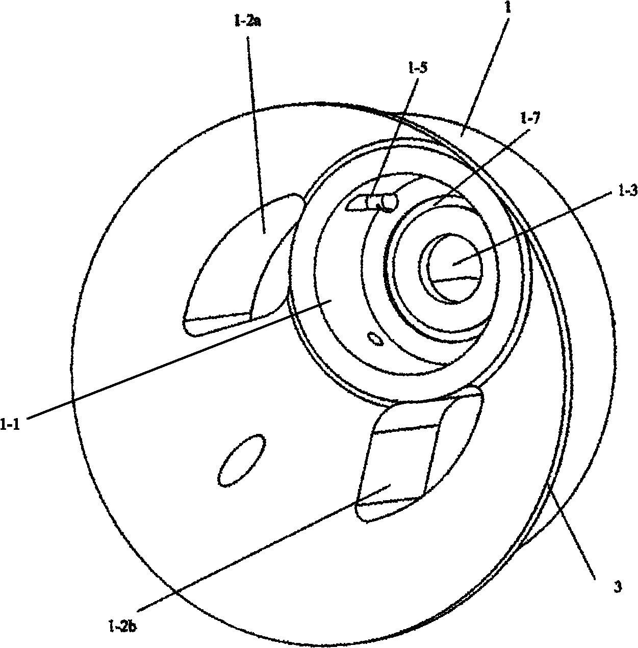
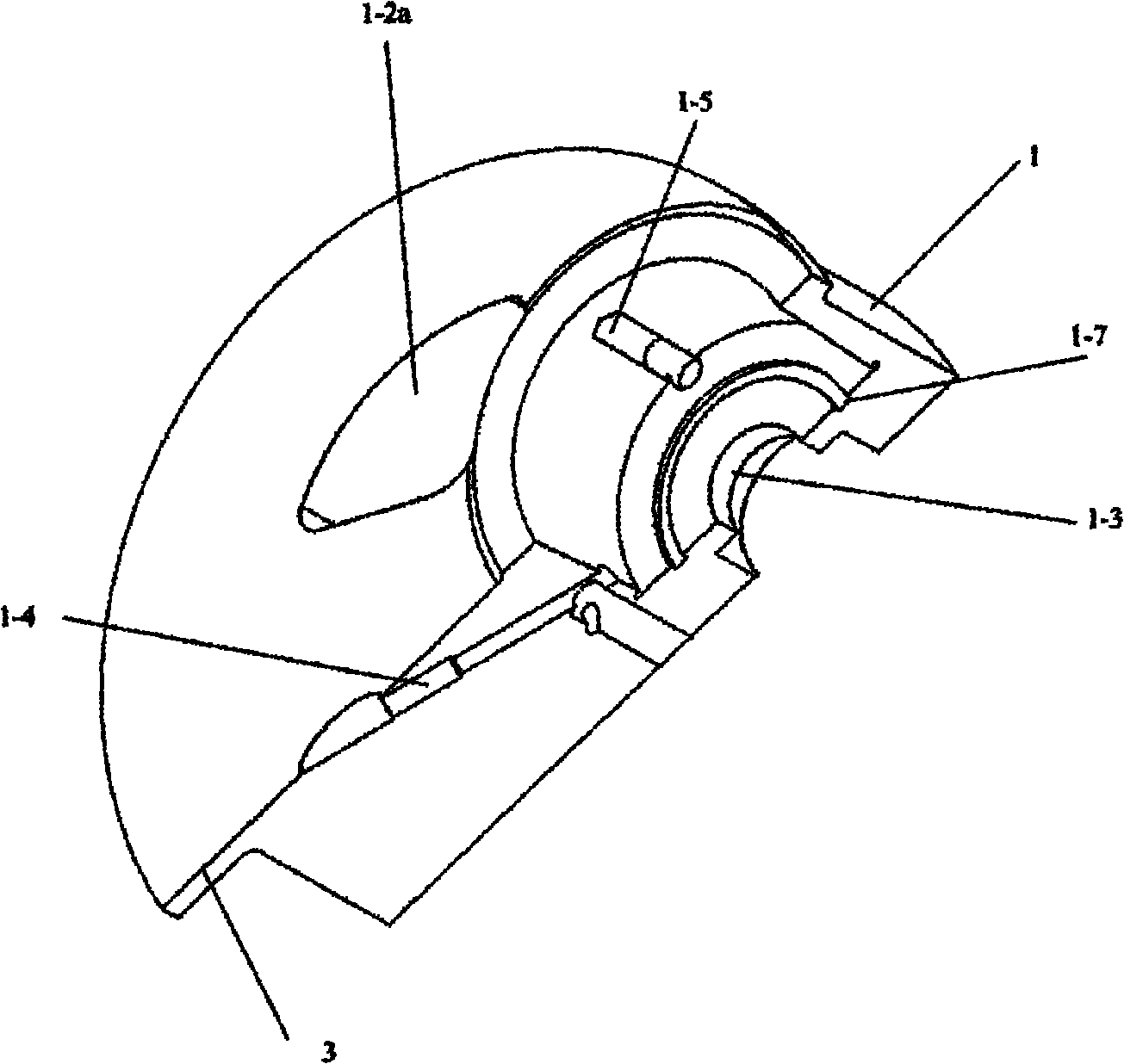
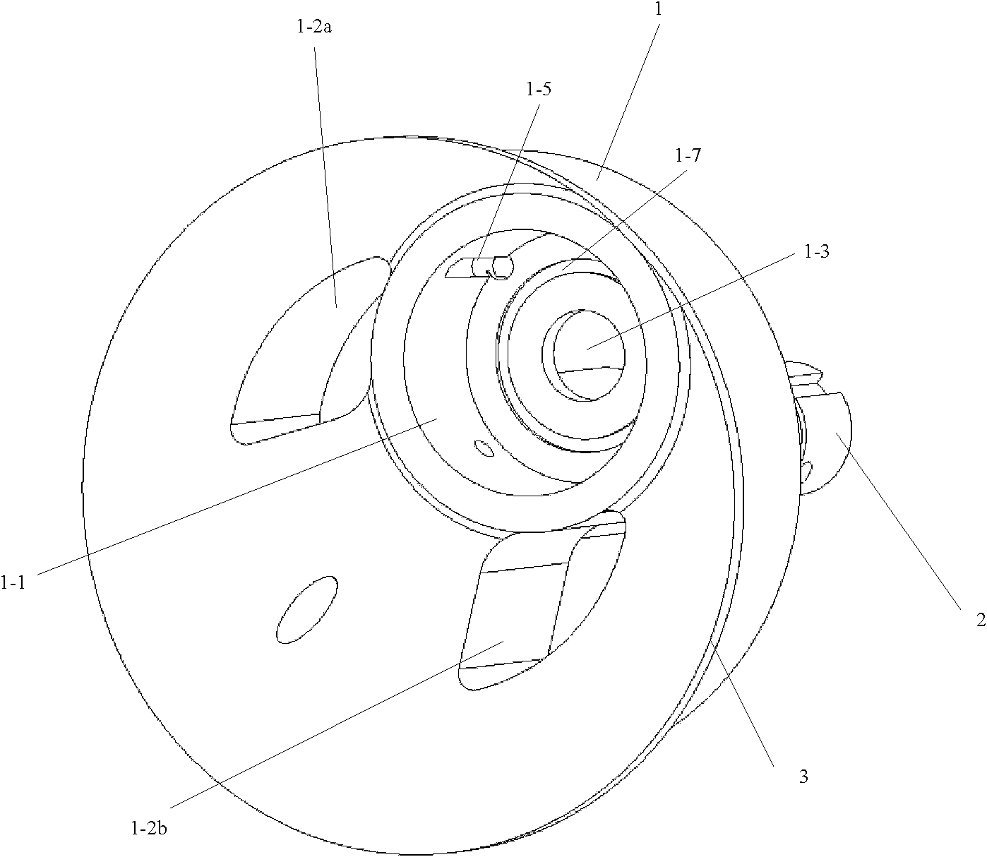
[0037] figure 1 It is one of the structural schematic diagrams of the embodiment of the crank of the present invention; figure 2 for figure 1 The schematic diagram of the crank shown after dissection.

[0038] Please refer to figure 1 with figure 2 , In the embodiment of the present invention, the crank 1 is a flat cylinder, including an outer peripheral surface and two opposite end surfaces.

[0039] The outer peripheral surface of the crank 1 can be directly sleeved with bearings, so that the crank and crank thr...


PUM


Abstract

The invention discloses a crank. The crank is an oblate cylinder, is provided with an eccentric hole of which the opening is formed on one end face of the crank, is used for accommodating the free end of a crankpin of a crank throw when an integral crankshaft is formed by assembling the crank together with the crank throw, and is named a crankpin mounting hole, wherein the central axis of the crankpin mounting hole is parallel to the central axis of the crank; the crankpin mounting hole is a choke plug hole; and a circular groove which is concentric with the end face of the bottom wall of themounting hole is formed on the bottom wall of the crankpin mounting hole and is named a force transmission groove. The force transmission groove is formed, so that the distribution of the pressing force between the bottom wall of the crankpin mounting hole and the end face of the free end of the crankpin can be improved, and the crankpin mounting hole is excellently attached to the free end of the crankpin. The invention also provides the crankshaft, a combined crankshaft using the crankshaft and an internal combustion engine or a compressor using the combined crankshaft.

Description

technical field [0001] The invention relates to an internal combustion engine or a compressor of a crank circular slider mechanism, in particular to a crank of the internal combustion engine or the compressor. The invention also relates to a crankshaft, a combined crankshaft using the crankshaft and an internal combustion engine or compressor using the combined crankshaft. Background technique [0002] In a traditional internal combustion engine, the reciprocating motion of the piston is converted into the rotational motion of the crankshaft through the crank-link mechanism, and then the crankshaft drives the corresponding moving parts to output power externally. In the traditional compressor, there is also a crank-link mechanism, through which the rotational motion of the crankshaft is converted into the reciprocating motion of the piston, and the air in the cylinder is compressed by the piston. However, in the crank-link mechanism, due to the existence of the connecting r...

Claims


Application Information

Patent Timeline
IPC IPC(8): F16C3/22F16C3/10F16C3/20F04B39/00
Inventor 王清旭黎明黎正中
Owner BEIJING SINOCEP ENGINE TECH
Why Eureka
Try Eureka