
Dynamic aperture module, lighting device and projector

A dynamic aperture and lighting device technology, applied to the aperture, camera, projection device, etc., can solve the problems of excessive flatness of the shading plate 610, burden of the motor 630, and abnormal noise caused by friction of surrounding components, etc., to achieve small assembly and movement space, best reliability effect

Inactive Publication Date: 2011-08-03
CORETRONIC
View PDF0 Cites 8 Cited by
  • Summary
  • Abstract
  • Description
  • Claims
  • Application Information

AI Technical Summary

Problems solved by technology

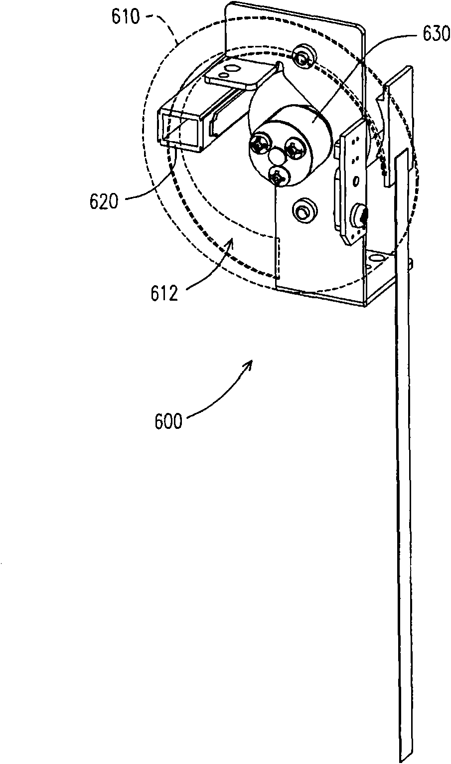
[0004] However, when the light beam irradiates the shading plate 610 and the shading plate 610 is in a high temperature state, since the shapes of the two sides of the slit 612 of the shading plate 610 are different, the degrees of thermal expansion are also different. Deformation will occur on both sides, and then the flatness of the visor 610 will exceed the preset value, and it will rub against surrounding components and make abnormal noises, and even cause the visor 610 to be stuck.
[0005] If the thickness and area of ​​the shading plate 610 are increased to make the shading plate 610 difficult to expand or strengthen the structure, the motor 630 will be burdened by the heavy weight of the shading plate 610, especially when the rotating speed of the shading plate 610 is fast, it is easy to be damaged due to Motor 630 out of step due to excessive moment of inertia

Method used


Image

  • Dynamic aperture module, lighting device and projector
  • Dynamic aperture module, lighting device and projector
  • Dynamic aperture module, lighting device and projector

Examples


Embodiment Construction

[0071] The aforementioned and other technical contents, features and effects of the present invention will be clearly presented in the following detailed descriptions of multiple embodiments with reference to the drawings. The directional terms mentioned in the following embodiments, such as "upper", "lower", "front", "rear", "left", "right", etc., are only referring to the directions of the attached drawings. Accordingly, the directional terms are used to illustrate, not to limit, the invention.

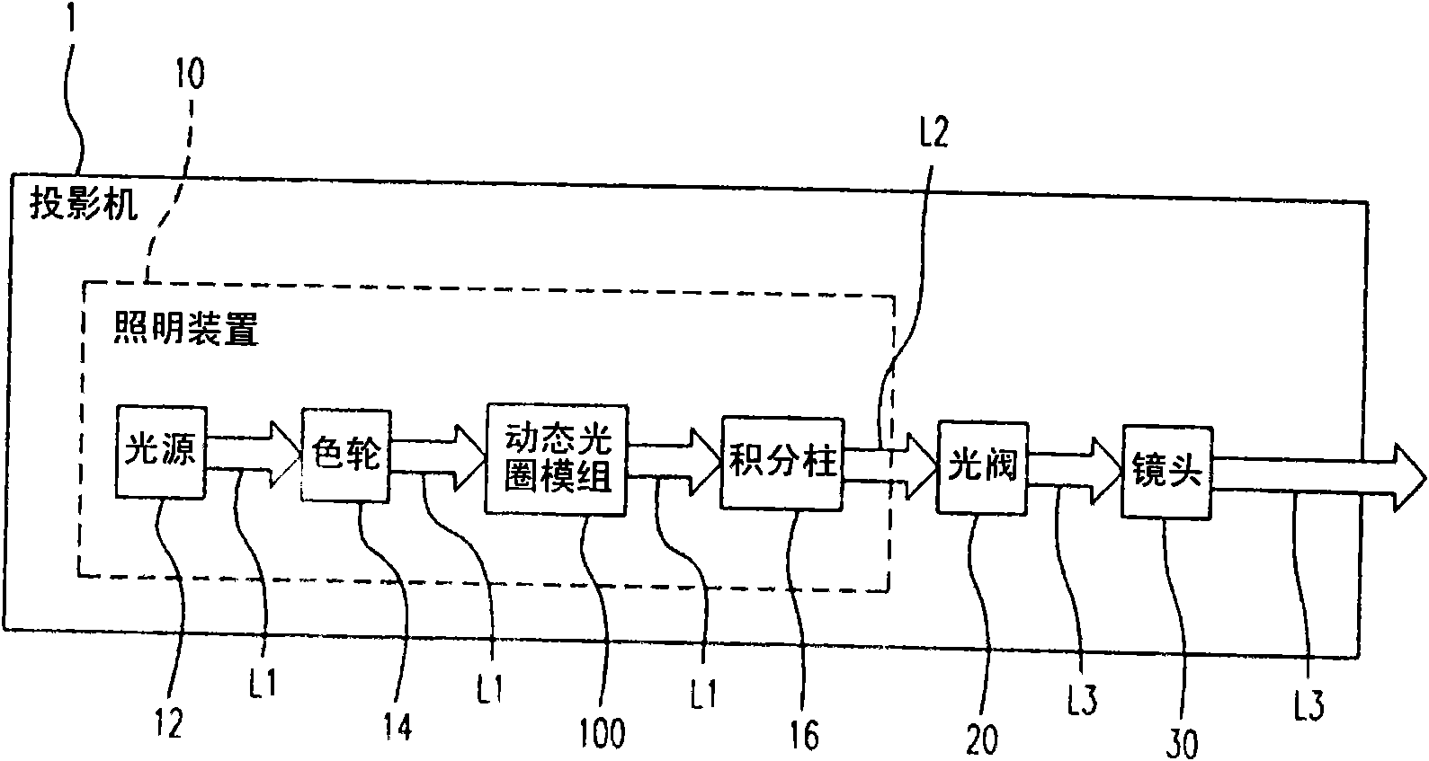
[0072] figure 2 It is a block diagram of a projector according to an embodiment of the present invention, wherein the arrows represent the light beams passing through each component in the projector in sequence. Please refer to figure 2 , the projector 1 includes an illumination device 10 , a light valve 20 and a lens 30 . The illuminating device 10 is adapted to provide an illuminating light beam L2. The light valve 20 is adapted to convert the illumination light beam L2 into...


PUM


Abstract

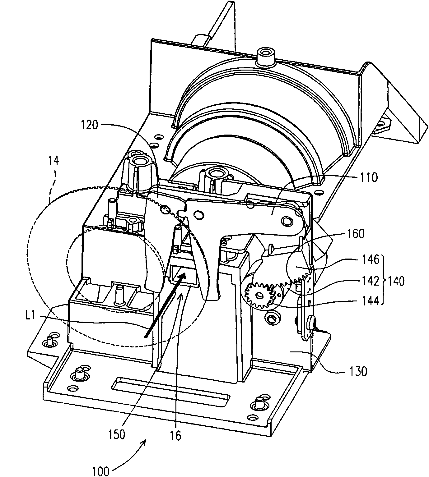
The invention relates to a dynamic aperture module, a lighting device and a projector. The projector comprises a lighting device, a light valve and a lens, wherein the lighting device comprises a light source for providing a beam, an integration rod, a color wheel and a dynamic aperture module, the dynamic aperture module is arranged between the integration rod and the color wheel and comprises a fixed seat, a first airflap, a second airflap and a driver; the first airflap and the second airflap are mutually coupled and respectively pivoted on the fixed seat; the driver is coupled to the first airflap; the driver drives the first airflap to rotate relative to the fixed seat so that the first airflap drives the second airflap to rotate; and the first airflap and the second airflap respectively rotate in opposite clockwise directions relative to the fixed seat to control the width of a gap between the first airflap and the second airflap and further adjust the luminous flux of a light beam passing through the gap.

Description

【Technical field】 [0001] The present invention relates to a dynamic aperture module, and in particular to a dynamic aperture module used for a lighting device in a projector. 【Background technique】 [0002] In recent years, with the development of projector technology, dynamic aperture modules have gradually been applied to projectors. The projector uses a dynamic aperture module to block part of the image beam, so as to move with images of different levels of light and dark, and then change the contrast of the image to achieve the purpose of improving the display quality. At present, the dynamic aperture module and related patents commonly used in projectors include China Taiwan Invention Patent Publication Nos. I307445, I245965, I256518, I258600, and I290260. [0003] figure 1 It is a schematic diagram of an existing dynamic aperture module in a projector. Please refer to figure 1 , the dynamic aperture module 600 includes a circular shading plate 610 , and the shading...

Claims


Application Information

Patent Timeline
IPC IPC(8): G03B9/06G03B21/20G03B21/00
Inventor 曾湧泉
Owner CORETRONIC
Learn More