Silicon controlled trigger circuit

A trigger circuit, thyristor technology, applied in electrical components, electronic switches, pulse technology, etc., can solve the problems of continuous thyristor off, false triggering, low commutation voltage and critical rate of rise of off-state voltage, etc. The effect of strong reliability, good reliability and low cost

Active Publication Date: 2011-08-03
常州汇邦电子有限公司
View PDF6 Cites 17 Cited by
  • Summary
  • Abstract
  • Description
  • Claims
  • Application Information

AI Technical Summary

Problems solved by technology

Its shortcoming is that driver chips such as MC3081 can only withstand low commutation voltage and critical rise rate of off-state voltage (dv / dt), which leads to problems such as continuous switching off of the thyristor and false triggering.

Method used


Image

  • Silicon controlled trigger circuit
  • Silicon controlled trigger circuit

Examples


Embodiment Construction

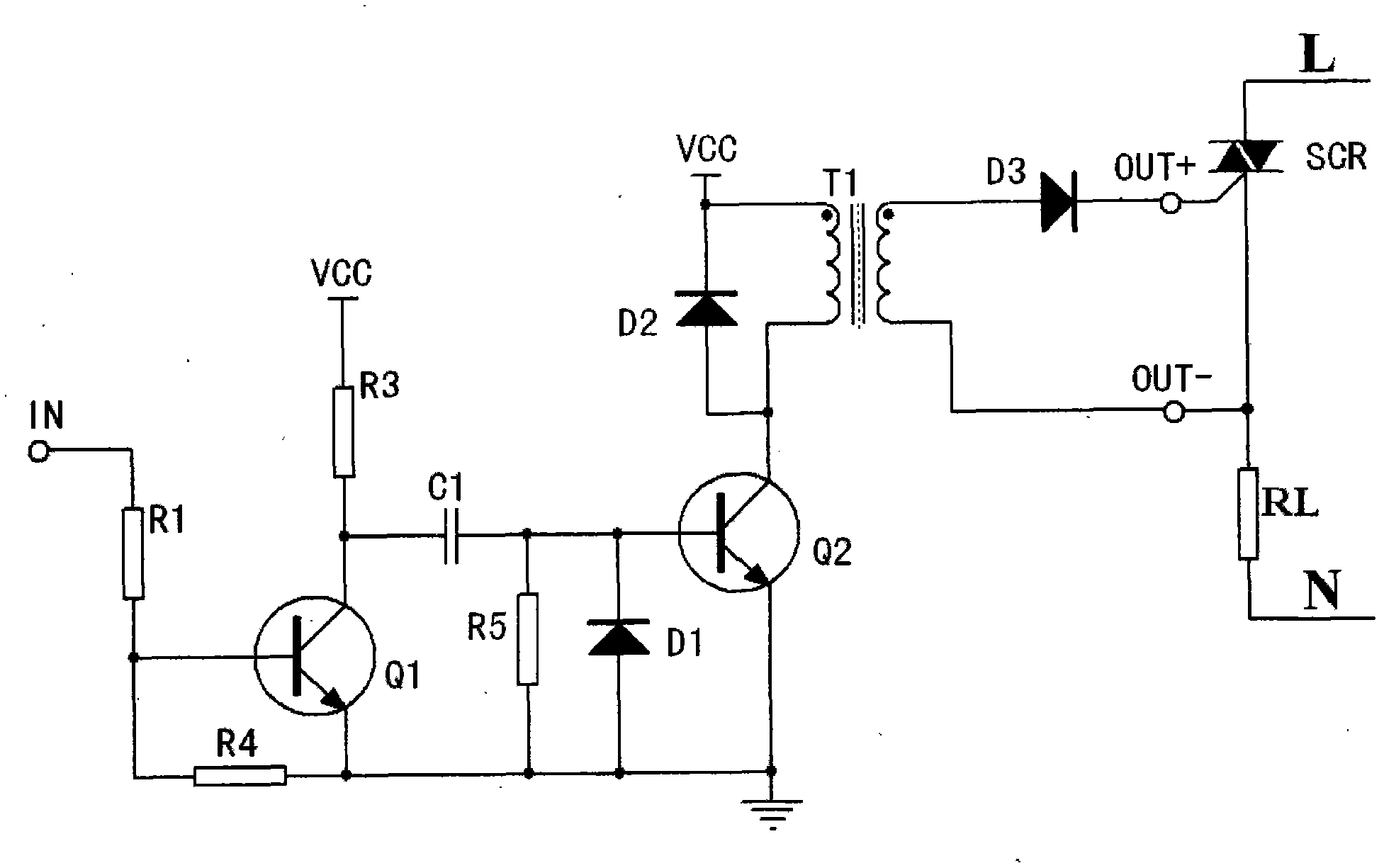
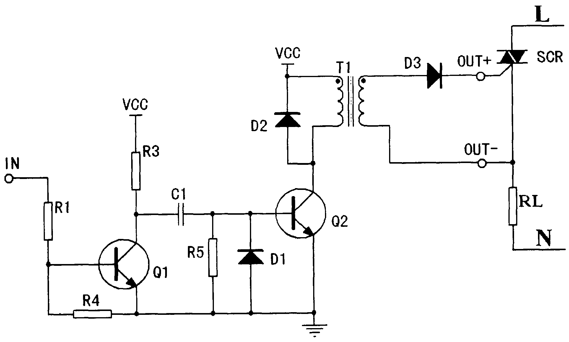
[0011] See figure 1 , the thyristor trigger circuit of this embodiment includes: a first triode Q1, a second triode Q2, a transformer T1, a capacitor C1 and a bidirectional thyristor SCR; the base of the first triode Q1 is connected to One end of the first resistor R1, and the other end of the first resistor R1 is the control signal input port IN; the collector of the first transistor Q1 is connected to the base of the second transistor Q2 through the capacitor C1, and the first transistor The collector of Q1 is connected to the DC power supply VCC through the current limiting resistor R3, and the emitters of the first transistor Q1 and the second transistor Q2 are grounded; the emitter of the first transistor Q1 is connected to the A fifth resistor R5 is connected between the bases; a fourth resistor R4 is provided between the base and the emitter of the first transistor Q1; the collector of the second transistor Q2 is connected to the primary coil of the transformer T1 One ...


PUM


Abstract

The invention relates to a bidirectional silicon controlled trigger circuit with low cost and better reliability. The bidirectional silicon controlled trigger circuit comprises a first audion, a second audion, a transformer, a capacitor and bidirectional silicon controlled, wherein the first audion is cut off when the input port of a control signal is in low electrical level, a direct-current power supply charges the capacitor to drive the second audion to be in saturated conductivity, the primary coil of the transformer is stimulated, so that the secondary coil of the transform outputs positive driving voltage by a third diode, the bidirectional silicon controlled is conducted, and the load is electrified; when the capacitor is completely charged, the second audion is cut off, the third diode is in the reverse cutoff state, and the load is in outage; when the input port of the control signal is controlled to be in high electrical level, the first audion is conducted, the capacitor, the first audion and a fifth resistor form a discharging circuit until electricity on the capacitor is completely discharged; and then, above steps are repeated when the input port of the control signal is in the low electrical level.

Description

technical field [0001] The invention relates to a thyristor trigger circuit. Background technique [0002] The existing silicon controlled rectifier trigger circuit often uses driver chips such as MC3081 to control the switching of the silicon controlled rectifier. The disadvantage is that driver chips such as MC3081 can only withstand low commutation voltage and critical rise rate of off-state voltage (dv / dt), which leads to problems such as constant switching off of the thyristor and false triggering. Contents of the invention [0003] The technical problem to be solved by the invention is to provide a thyristor trigger circuit with simple structure, low cost and good reliability. [0004] In order to solve the above-mentioned technical problems, the present invention provides a thyristor trigger circuit, which is characterized by comprising: a first triode Q1, a second triode Q2, a transformer T1, a capacitor C1 and a bidirectional thyristor SCR; The base of the first...

Claims


Application Information

Patent Timeline
Patent Type & Authority Applications(China)
IPC IPC(8): H03K17/72
Inventor 陈冲王兴强孙明宏
Owner 常州汇邦电子有限公司
Why Eureka
Try Eureka