Rotary lifting appliance of electromagnetic plate crane

A technology of rotating spreader and crane, applied in the direction of load hanging components, transportation and packaging, etc., can solve the problems of unreasonable structure design, poor sealing, complicated structure of rotating spreader, etc., to achieve fewer failure points and reduce the number of parts and components. , the effect of convenient maintenance

Active Publication Date: 2011-08-10
TAIYUAN HEAVY IND
View PDF4 Cites 4 Cited by
  • Summary
  • Abstract
  • Description
  • Claims
  • Application Information

AI Technical Summary

Problems solved by technology

[0004] The purpose of the present invention is to overcome the deficiencies of the prior art, provide a rotary hoist for an electromagnetic disk crane, and solve the problems of the existing rotary hoist with complex structure, unreasonable structural design, and poor sealing performance

Method used


Image

  • Rotary lifting appliance of electromagnetic plate crane
  • Rotary lifting appliance of electromagnetic plate crane
  • Rotary lifting appliance of electromagnetic plate crane

Examples


Embodiment Construction

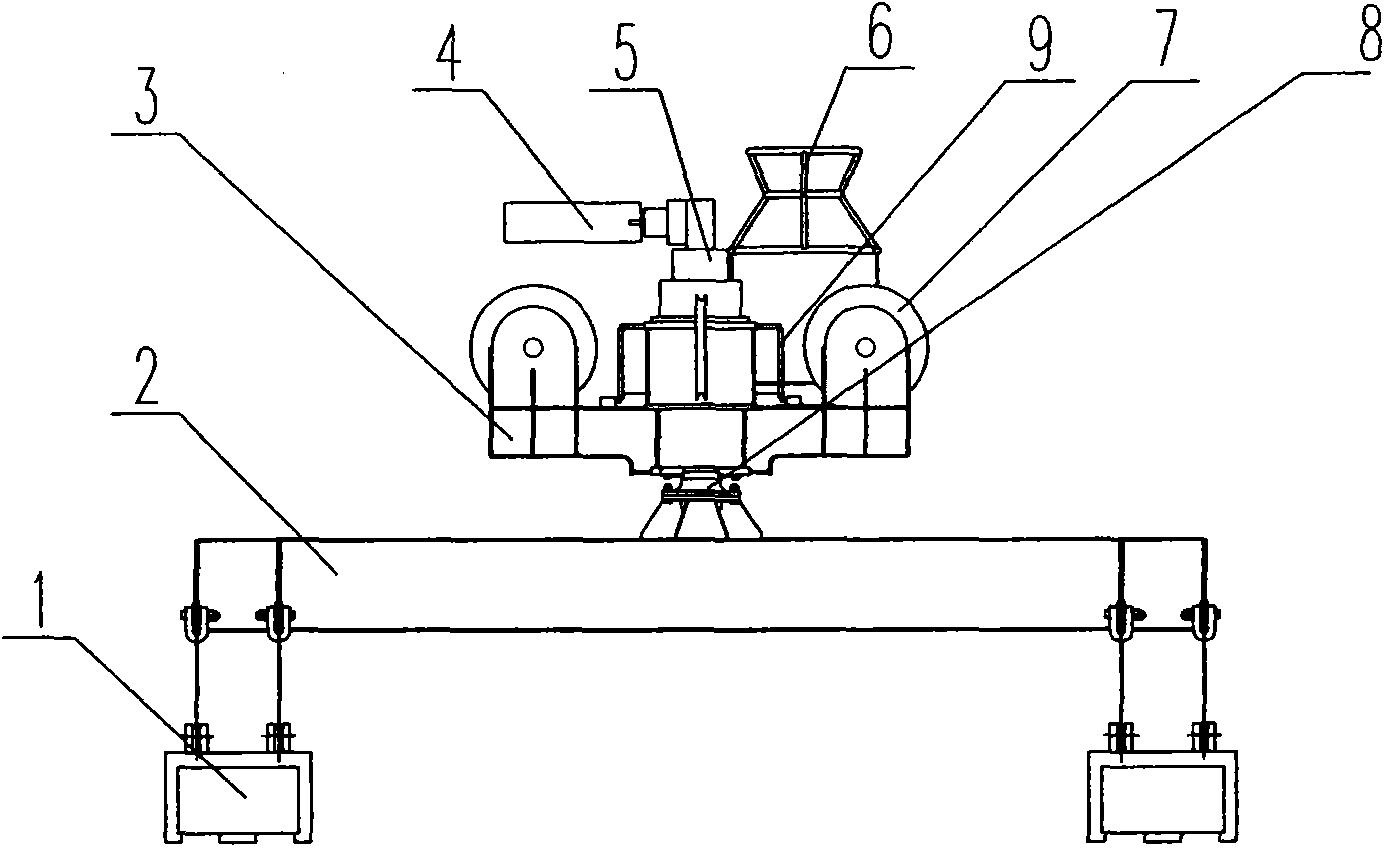
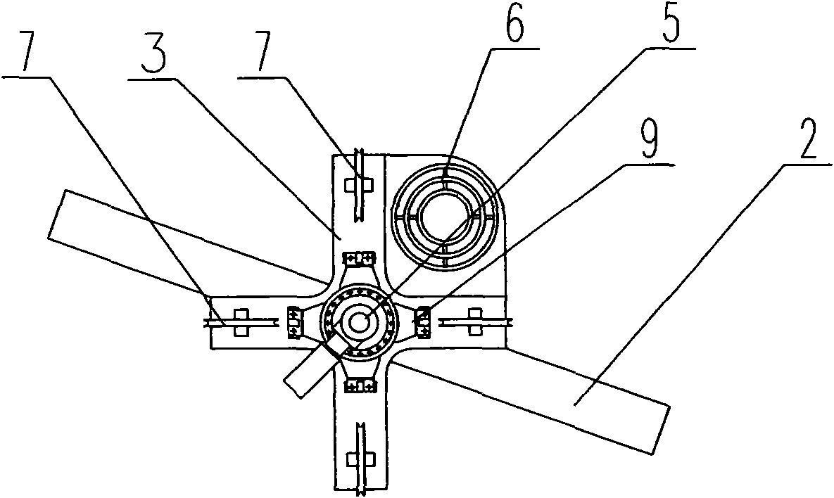
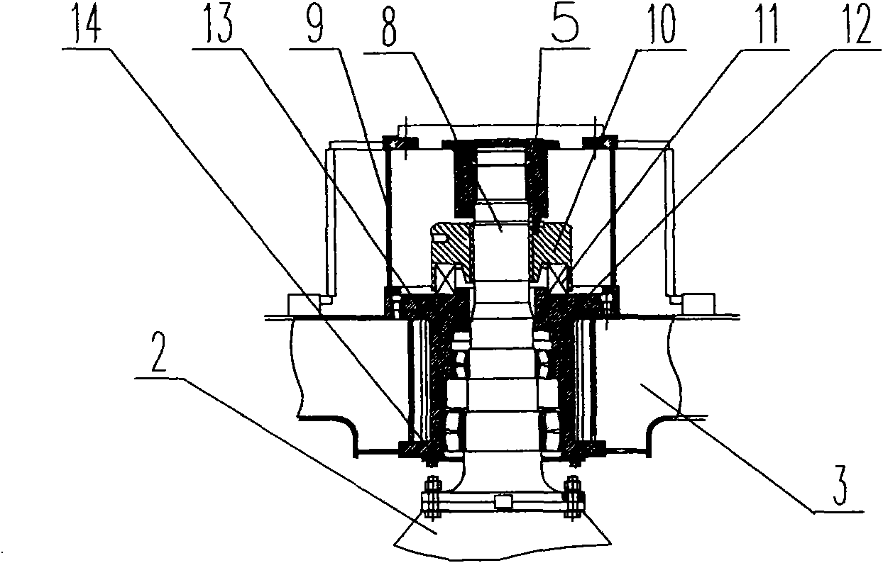
[0020] Such as figure 1 , 2 As shown in , 3, a rotating hoist for an electromagnetic disk crane includes: an electromagnetic hanging beam 2, an electromagnetic disk 1 that is flexibly connected to the lower end of the electromagnetic hanging beam 2, and is characterized in that: the electromagnetic hanging beam 2 is provided with a The crossbeam 3 connected by the driving mechanism of the rotating sling, the driving mechanism of the rotating sling consists of a motor 4, a reducer 5, a rotating shaft 8, a reducer support 9, a hook nut 10, a thrust bearing 11, and a bearing seat 12 , a positioning bearing 13, and a sealing flange 14; the motor 4 drives the reducer 5, the inner spline of the output shaft of the reducer 5 cooperates with the outer spline of the rotating shaft 8 to drive the rotating shaft 8 to rotate, The lower end flange of the rotating shaft 8 is bolted to the end flange of the electromagnetic hanging beam 2, the upper thread of the rotating shaft 8 is connecte...


PUM


Abstract

The invention discloses a rotary lifting appliance of an electromagnetic plate crane and relates to the electromagnetic plate crane. By the rotary lifting appliance, the problems of complex structure, unreasonable structure design and poor sealing performance of the existing rotary lifting appliance are solved. A cross beam connected with a driving mechanism of the rotary lifting appliance is arranged above an electromagnetic suspended beam. A motor drives a speed reducer. An internal spline of an output shaft of the speed reducer is matched with an external spline of a rotating shaft to drive the rotating shaft to rotate. A flange at the lower end of the rotating shaft is connected with a flange at the end part of the electromagnetic suspended beam through a bolt. Screw threads at the upper part of the rotating shaft are connected with a lifting hook nut. A thrust bearing is arranged between the lifting hook nut and a bearing support which is sleeved on the rotating shaft and is connected with the cross beam. The lower end of the bearing support is provided with a sealing flange and is matched with the rotating shaft. A positioning bearing is also arranged between the bearing support and the rotating shaft.

Description

technical field [0001] The invention relates to an electromagnetic disk crane, in particular to a rotating hanger of the electromagnetic disk crane. Background technique [0002] At present, the electromagnetic disk cranes used for hoisting or stacking finished steel materials use two lifting points to rotate the spreader to place the steel materials, or to rotate and place the steel materials by the rotating mechanism matched with the crane lifting mechanism. [0003] The driving mechanism of the rotating spreader of the existing electromagnetic disk crane mostly adopts the output long shaft of the reducer to drive the pinion to rotate, and the pinion and the large gear cooperate to drive the rotation of the electromagnetic hanging beam to realize the rotation of the spreader. This kind of rotary spreader has a complex structure, the gear meshing surface is exposed to the air, the lubrication is not good, and the gear wears quickly. Contents of the invention [0004] The...

Claims


Application Information

Patent Timeline
Patent Type & Authority Applications(China)
IPC IPC(8): B66C13/08B66C1/06
Inventor 闫俊峰李万录
Owner TAIYUAN HEAVY IND
Why Eureka
Try Eureka