Air vent structure of oil pump of automatic transmission

一种自动变速器、油泵的技术,应用在泵、旋转活塞式/摆动活塞式的泵组合、旋转活塞式/摆动活塞式的泵部件等方向,达到高响应性的效果

Active Publication Date: 2011-08-10
JATCO LTD +1
View PDF8 Cites 15 Cited by
  • Summary
  • Abstract
  • Description
  • Claims
  • Application Information

AI Technical Summary

Problems solved by technology

[0009] That is, there is a problem that although the air discharge hole is provided for the purpose of discharging the sucked air, the air sucked in through the air discharge hole is sent out from the auxiliary pump to the control valve and the lubricating part instead.

Method used


Image

  • Air vent structure of oil pump of automatic transmission
  • Air vent structure of oil pump of automatic transmission
  • Air vent structure of oil pump of automatic transmission

Examples


no. 1 example

[0064] First, the first embodiment will be described.

[0065] A hybrid vehicle is equipped with, as a drive source, an engine and an electric motor connected to an automatic transmission via a torque converter, and the engine and the electric motor are switched or used in combination according to driving conditions.

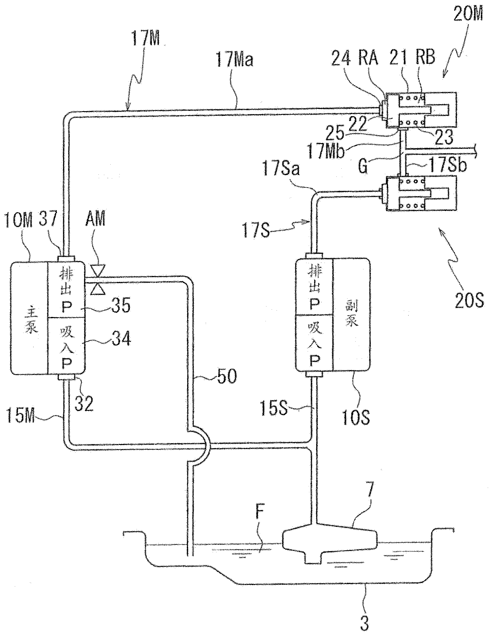
[0066] Such as figure 1 As shown, the oil pump for internal lubrication of an automatic transmission is provided with a main pump 10M and a sub pump 10S. The suction oil passages of the main pump 10M and the sub pump 10S merge and connect to the oil filter 7, and the discharge oil passages of the main pump 10M and the sub pump 10S also merge and connect to various lubricating parts and control valves not shown in the figure.

[0067] In the figure, the suction P is the suction port, and the discharge P is the discharge port.

[0068] The main pump 10M is arranged between the hydraulic torque converter and the automatic transmission. As will be described later...

no. 2 example

[0118] The second embodiment is an example in which the form of the air discharge hole is different. Since only the oil pump cover is different, descriptions will be made using the same symbols as those of the first embodiment except for the oil pump cover.

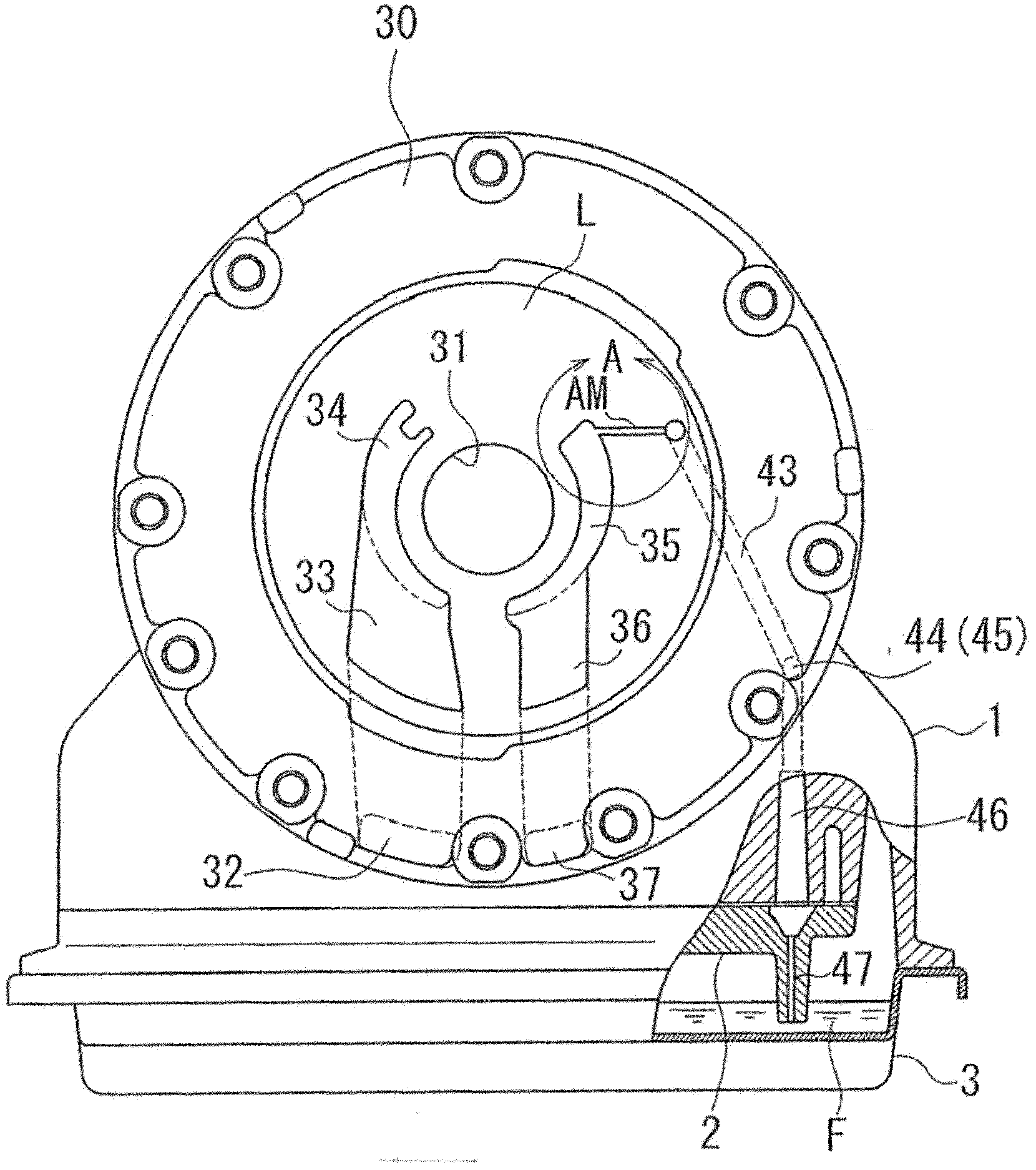
[0119] Figure 5 It is a front view of the oil pump cover 30' of the main pump 10M of this embodiment attached to the transmission case 1 seen from the torque converter side.

[0120] An air discharge hole AM' communicating with the discharge port and extending in the axial direction is provided at the starting end of the discharge port 35 .

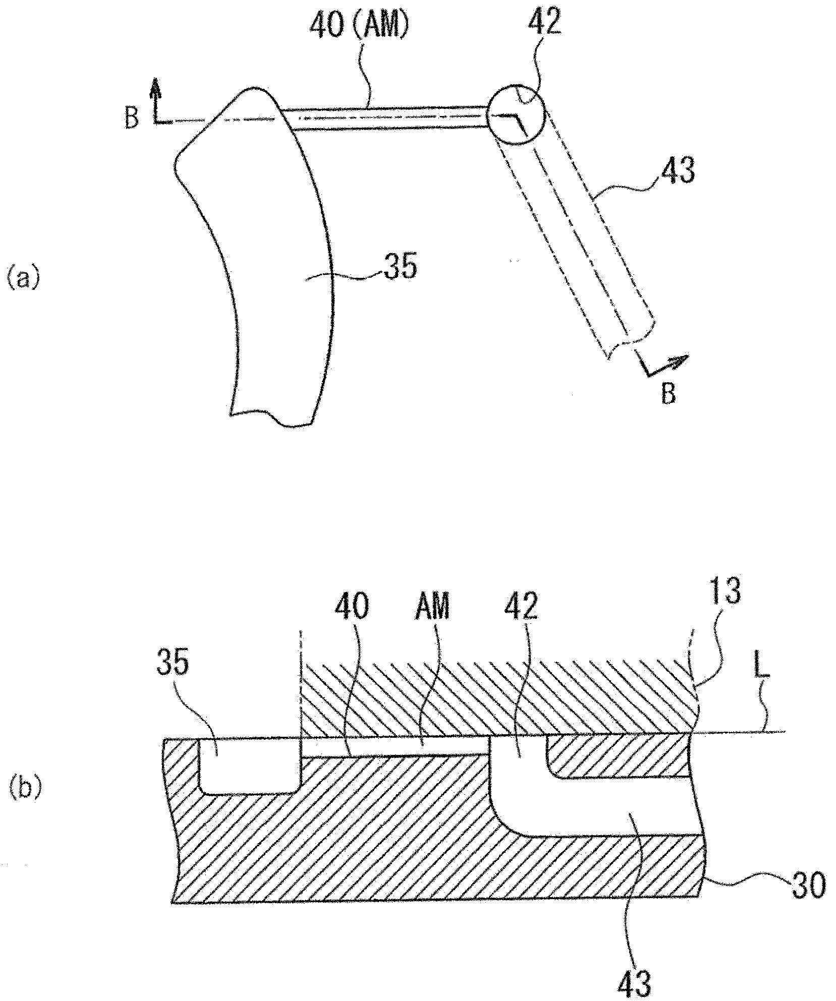
[0121] Image 6 (a) is an enlarged front view showing a portion C around the discharge port 35 of the oil pump cover 30', Image 6 (b) is Image 6 An enlarged cross-sectional view of D-D part of (a).

[0122] The air discharge hole AM' is, for example, an orifice with a diameter of 0.2 mm or less, through which air can easily pass, but becomes resistance to the passage of visco...


PUM


Abstract

An air vent structure of an oil pump of automatic transmission. In a hybrid vehicle loaded with a primary pump and a secondary pump, the air is not sucked from an air vent of the primary pump when the secondary pump works. A suction oil path and a discharge oil path of the primary pump (10M) and the secondary pump (10S) are connected in parallel. In the discharge oil paths (17M, 17S), the accumulators 20M, 20S are disposed upstream of junction G to cut off the discharge oil path driving the pump on the stop side. An air vent (AM) is disposed on a discharge port 35 of the primary pump (10M) and is communicated with thw oil (F) of an oil pan (3) through a communication passage (50). Therefore, the state of the primary pump filled with the oil maintains a certain period because the main discharge passage 17M is cut off, even if the primary pump (10M) stops and the responsivity of recovering the operation is enhanced; and in addition, the air vent (AM) is communicated with the oil pan, there is impossible to suck the air in operation later.

Description

technical field [0001] The present invention relates to an exhaust structure of an oil pump of an automatic transmission. Background technique [0002] In an automatic transmission using a torque converter for vehicles, an oil pump driven by a sleeve extending from an impeller connected to an output shaft of an engine supplies oil to each lubricating portion in the transmission mechanism. [0003] The oil pump sucks oil from the oil pan installed in the lower part of the transmission case to the suction port through the suction oil passage equipped with the oil filter, and sends oil from the discharge port to the control valve and the lubricating parts through the discharge oil passage. [0004] Recently, with the hybridization of the vehicle drive system, in order to ensure the supply of oil to the lubricating part during the period when the oil pump is not driven by the engine, a sub pump is provided. The sub pump has a suction oil passage for the oil pump (main pump) And...

Claims


Application Information

Patent Timeline
Patent Type & Authority Applications(China)
IPC IPC(8): F04C15/00F04C11/00F16H57/04
CPCF16H2061/0037F16H57/0436F16H57/0446F16H57/0443F16H61/0031Y10T74/2186
Inventor 大村智洋
Owner JATCO LTD
Why Eureka
Try Eureka