Magnetic sensor device

A magnetic sensor and sensor technology, applied in the direction of measuring devices, magnetic performance measurement, instruments, etc., can solve the problem that the magnetic properties of the medium 1 cannot be detected

Inactive Publication Date: 2011-08-10
SANKYO SEIKI MFG CO LTD
View PDF6 Cites 31 Cited by
  • Summary
  • Abstract
  • Description
  • Claims
  • Application Information

AI Technical Summary

Problems solved by technology

Therefore, when the width of the magnetic region 1a of the medium 1 is narrow, if the medium 1 deviates in the medium width direction Y and pa

Method used


Image

  • Magnetic sensor device
  • Magnetic sensor device
  • Magnetic sensor device

Examples


Embodiment approach

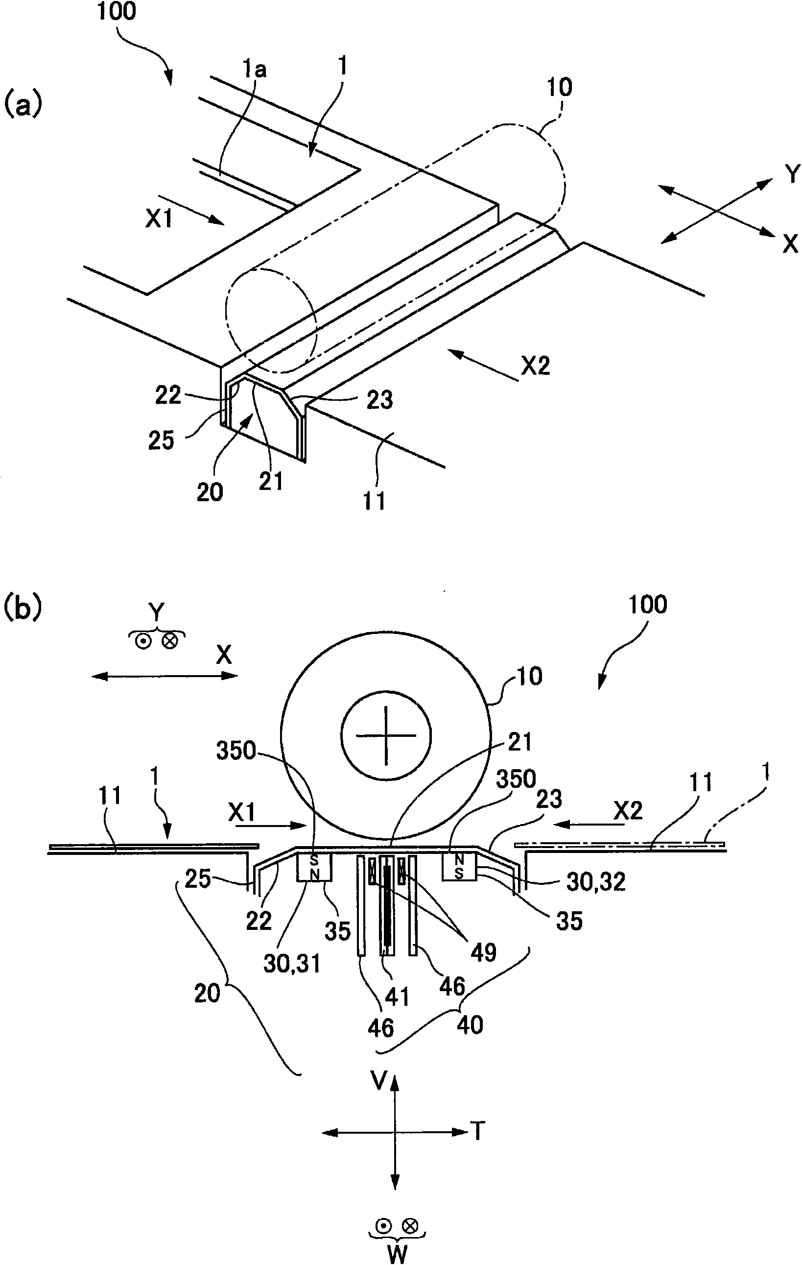
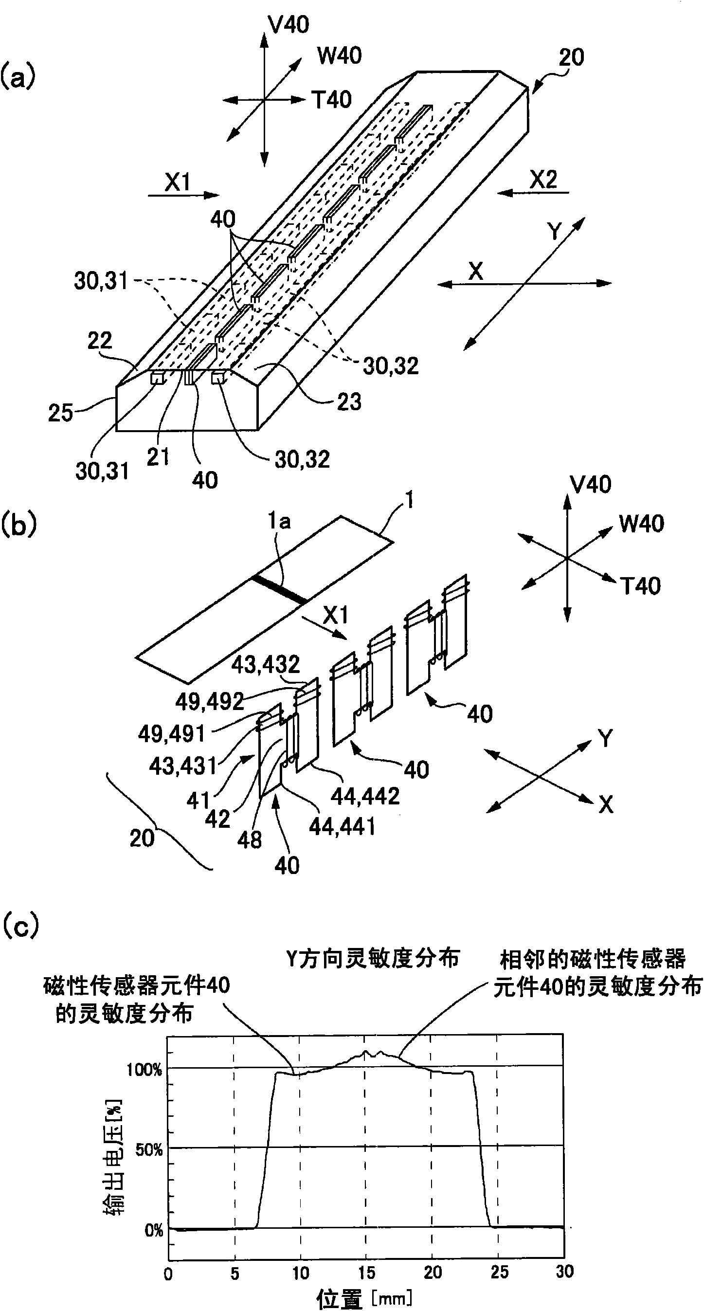
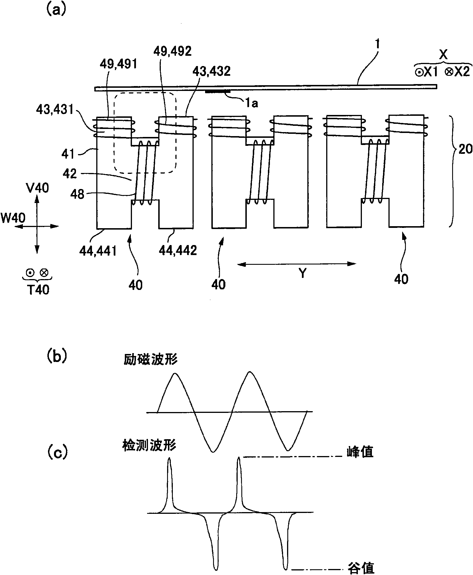
[0087] Figure 9 It is an explanatory diagram using the magnetic sensor element 40 used in the magnetic sensor device 20 according to another embodiment of the present invention, Figure 9 (a), (b), and (c) are explanatory diagrams when the number of magnetic-collection protrusions 43 is three, explanatory diagrams when the number of magnetic-collection protrusions 43 is four, and magnetic-collection protrusions Explanatory diagram when the number of 43 is 5.

[0088] refer to Figure 1 to Figure 8 In the magnetic sensor element 40 described, two protrusions 43 for collecting magnetism are formed on the sensor core 41, but it may also be as follows: Figure 9 As shown in (a), (b), and (c), a configuration is adopted in which three or more protrusions 43 for magnetic flux collection protrude from the main body 42 of the sensor core 41 . In the case of adopting such a structure, as in the above-mentioned embodiment, the detection coils 49 are respectively wound on the protrus...


PUM


Abstract

The invention provides a magnetic sensor device which can enlarge the detection range in a medium width direction which is orthogonal to a medium moving direction. In a sensor magnetic core of a magnetic sensor component, a plurality of magnetic matrix protruding parts (431, 432) which protrudes from a main body extending in a width direction W40 to one side of a medium moving path are mutually separated in a width direction W40. The plurality of magnetic matrix protruding parts are reeled with detection coils (491, 492), and the main body is reeled with an excitation coil. The magnetic sensor component is configured in that a thickness direction T40 which is orthogonal to the width direction W40 and the protruding direction of the magnetic matrix protruding parts (height direction V40) faces towards the moving direction X of the medium. The magnetic matrix protruding parts and the detection coils are disposed at a division position of a medium width direction Y which is orthogonal to the medium moving direction.

Description

technical field [0001] The present invention relates to a magnetic sensor device for detecting the magnetic characteristics and the like of an object mounted with a magnetic body and a banknote printed with magnetic ink. Background technique [0002] When detecting the magnetic characteristics of objects such as cards equipped with magnetic substances, and banknotes printed with magnetic ink, etc., a magnetic sensor device including a magnetic sensor element is provided in the middle of the conveyance path of the medium. (Refer to Patent Document 1). [0003] In the magnetic sensor device described in Patent Document 1, the magnetic sensor element such as Figure 11 As shown in (a), it has a structure in which the coils 93 and 94 are wound around the sensor core 91 . In the sensor core 91 , a plurality of protrusions 911 to 916 protrude from the main body 910 extending in the width direction W90 of the magnetic sensor element 90 toward the medium moving path 11 side of the ...

Claims


Application Information

Patent Timeline
IPC IPC(8): G07D7/04G01R33/16
CPCG01R33/02G01R33/09G07D7/01G07D7/04
Inventor 百濑正吾
Owner SANKYO SEIKI MFG CO LTD
Why Eureka
Try Eureka