Change-over switch gear

A transfer switch and switch technology, applied in the direction of contact drive mechanism, etc., can solve the problems of switch closing, opening failure, gear stuck, large impact of hinge point, etc., to achieve the effect of ensuring reliability and smooth meshing

Active Publication Date: 2013-10-09
CHANGSHU SWITCHGEAR MFG CO LTD (FORMER CHANGSHU SWITCHGEAR PLANT)
View PDF4 Cites 0 Cited by
  • Summary
  • Abstract
  • Description
  • Claims
  • Application Information

AI Technical Summary

Problems solved by technology

[0005] As described in Chinese patent 97191864.3, a switch device such as a transfer switch for electrical equipment discloses a transfer switch device that uses a link cam mechanism for transmission. The two circuit breakers are installed up and down, and the discs correspond to the two The circuit breakers are installed up and down, and are respectively connected with a set of mechanical devices for driving the corresponding circuit breakers. The disc is hinged to one end of the connecting rod, and the other end of the connecting rod is hinged to the small driving connecting rod through the second journal. , the other end of the small driving link is hinged with a pivot pin, and the pivot pin drives the contact system in the circuit breaker to open and close. The above structure can be changed by changing the pivot position of the link on the disc and combining the The respective sets of mechanical devices realize the interlocking function between the circuit breakers. However, due to the uneven force of the connecting rod cam mechanism during the transmission process, the impact on each hinge point is relatively large, which will cause the gap between each hinge point to be affected by the mechanism. The influence of the action impact becomes larger, which causes the fatigue deformation of the connecting rod, and even the failure of the transmission and chain
[0006] As described in the Chinese patent 200910047109, the three-gear conversion mechanism of the transfer switch electric appliance specifically discloses a gear transmission mechanism, including: a first gear A connected to the first contact, and the rotation of the first gear drives the first contact Close or open with the first power supply; the second gear B is connected to the second contact, the rotation of the second gear drives the second contact to close or open with the second power supply, the first gear does not contact the second gear; the driving gear C , Mesh to the first gear to drive the first gear to rotate, and mesh to the second gear to drive the second gear to rotate. The above structure uses the different meshing conditions of the gear sets to realize the position conversion. The disadvantage is that the A and B gears are affected by vibration or Affected by other factors, the A and B gears may be slightly deflected, and when the first gear A or the second gear B and the driving gear C start to mesh, the first meshing teeth on the first gear A or the second gear B and the driving gear C The tooth tops of the first meshing teeth on gear C will collide with each other, causing the gears to be stuck, and the meshing failure will lead to the failure of the switch to close and open, and the chain failure between the first contact and the second contact formed by the three-gear conversion mechanism

Method used


Image

  • Change-over switch gear
  • Change-over switch gear
  • Change-over switch gear

Examples


Embodiment Construction

[0038] The accompanying drawings disclose non-restrictive structural schematic diagrams of preferred embodiments involved in the present invention, and the technical solutions of the present invention will be described in detail below in conjunction with the accompanying drawings.

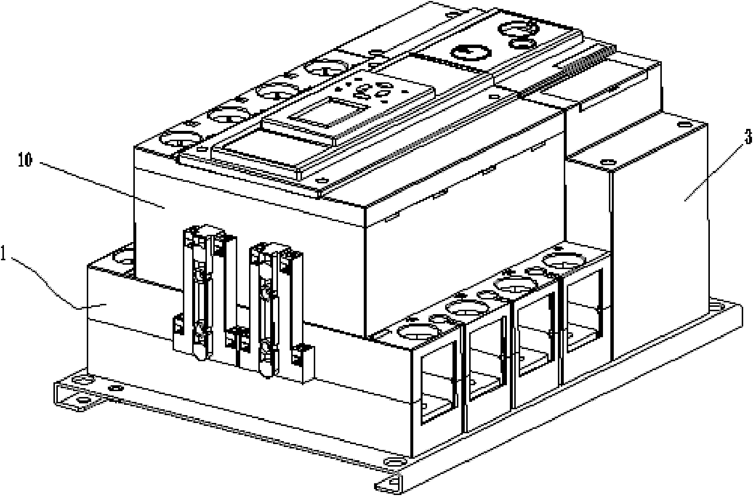
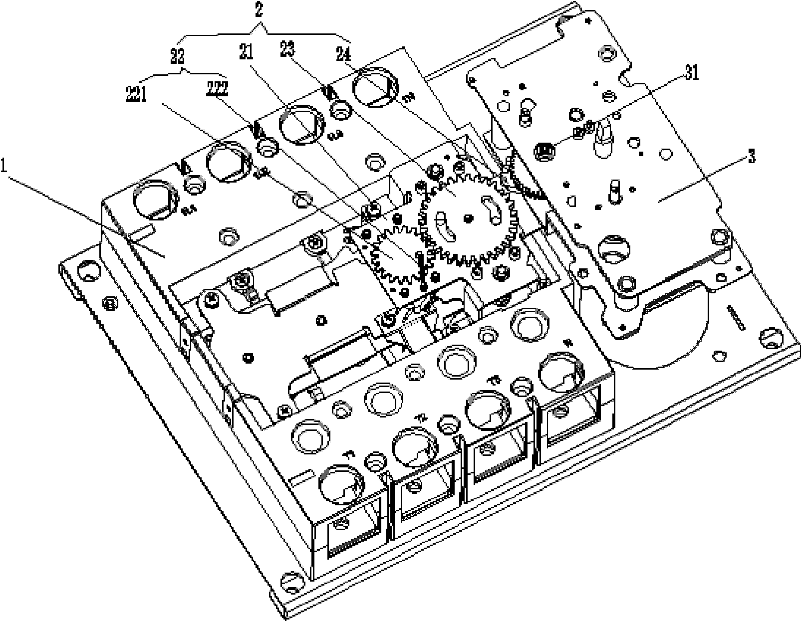
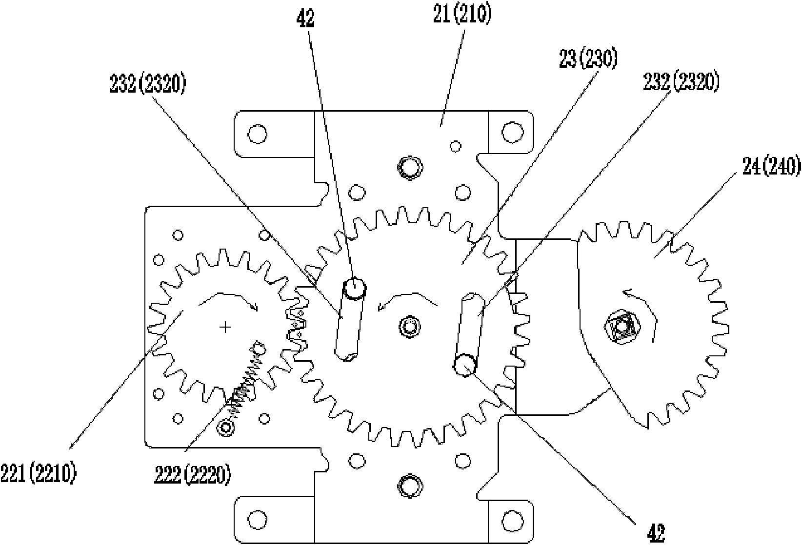
[0039] As shown in Figures 1 to 12, the changeover switch device of the present invention includes two switch bodies 1, 10 stacked up and down, a driving motor 3 with an output shaft 31, and a gear with gears inside each switch body. The spring energy storage mechanism connected to the transmission mechanism 2 includes an energy storage spring 41 and a pivot 42 .

[0040] The gear transmission mechanism 2 includes two brackets 21, 210 respectively fixed on the switch bodies 1, 10, reset gear assemblies 22, 220 respectively arranged on the brackets 21, 210, respectively pivoted on the brackets 21, 210 and connected with the reset gear assembly. The switch gears 23, 230 meshed with the gear assemblie...


PUM


Abstract

The invention discloses a change-over switch gear, comprising a base, wherein the base is respectively provided with a driving motor and two switch bodies which are stacked up and down, each switch body is connected with a gear transmission mechanism, each gear transmission mechanism comprises a support fixedly arranged on the switch body, a resetting gear assembly, a switch gear and a sector gear, the resetting gear assembly comprises a resetting gear and a resetting spring, the two ends of the resetting spring are respectively connected with the resetting gear and the support, the sector gear is connected with the driving motor, the switch gear is respectively meshed with the teeth of the resetting gear and the teeth of the sector gear, and the sector gears of another two gear transmission mechanisms are coaxially pivoted and the teeth of the two sector gears are arranged back to back. Thus, gearing mesh and even the whole mechanical transmission are ensured to be stable and reliable, and the reliability of mechanical interlocking is ensured.

Description

technical field [0001] The invention relates to a transfer switch device, in particular to a transfer switch device which improves a gear transmission mechanism to prompt the switch device to perform power switching, and belongs to the technical field of electric appliances. Background technique [0002] In many important power supply occasions, such as airports, docks, hospitals, etc. In order to ensure the safe and reliable operation of the load, it is necessary to install an automatic transfer switch device to meet the continuity of power supply in the above occasions. [0003] The transmission mechanism is an important component in the automatic transfer switch device, and its interlocking function ensures that the normal and standby power sources will not be connected at the same time. [0004] At present, the transmission mechanism of the automatic transfer switch device mostly adopts a connecting rod cam mechanism. [0005] As described in Chinese patent 97191864.3,...

Claims


Application Information

Patent Timeline
Patent Type & Authority Patents(China)
IPC IPC(8): H01H3/32H01H3/40
Inventor 丁晓辉管瑞良周振忠顾怡文
Owner CHANGSHU SWITCHGEAR MFG CO LTD (FORMER CHANGSHU SWITCHGEAR PLANT)
Why Eureka
Try Eureka