Method and system for testing multi-antenna terminal

A test method and test system technology, applied in diversity/multi-antenna system, wireless communication, telephone communication and other directions, can solve the problem of inability to test and evaluate the radio frequency performance of multi-antenna terminals in space

Inactive Publication Date: 2011-08-10
ZTE CORP
View PDF2 Cites 10 Cited by
  • Summary
  • Abstract
  • Description
  • Claims
  • Application Information

AI Technical Summary

Problems solved by technology

[0005] In view of this, the main purpose of the present invention is to provide a multi-antenna terminal testing method and system to solve the problem that traditional darkrooms cannot test and evaluate the space radio frequency performance of multi-antenna terminals

Method used


Image

  • Method and system for testing multi-antenna terminal
  • Method and system for testing multi-antenna terminal
  • Method and system for testing multi-antenna terminal

Examples


Embodiment Construction

[0038] The technical solutions of the present invention will be further elaborated below in conjunction with the accompanying drawings and specific embodiments.

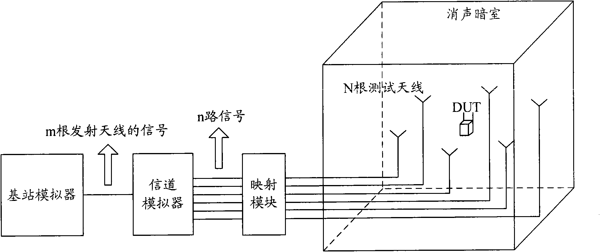
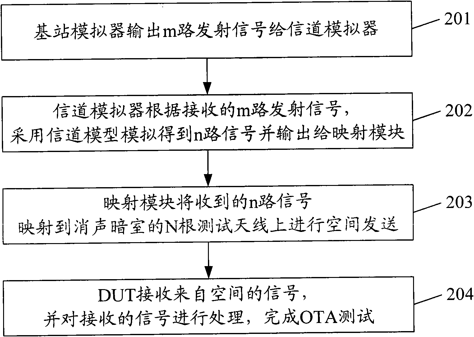
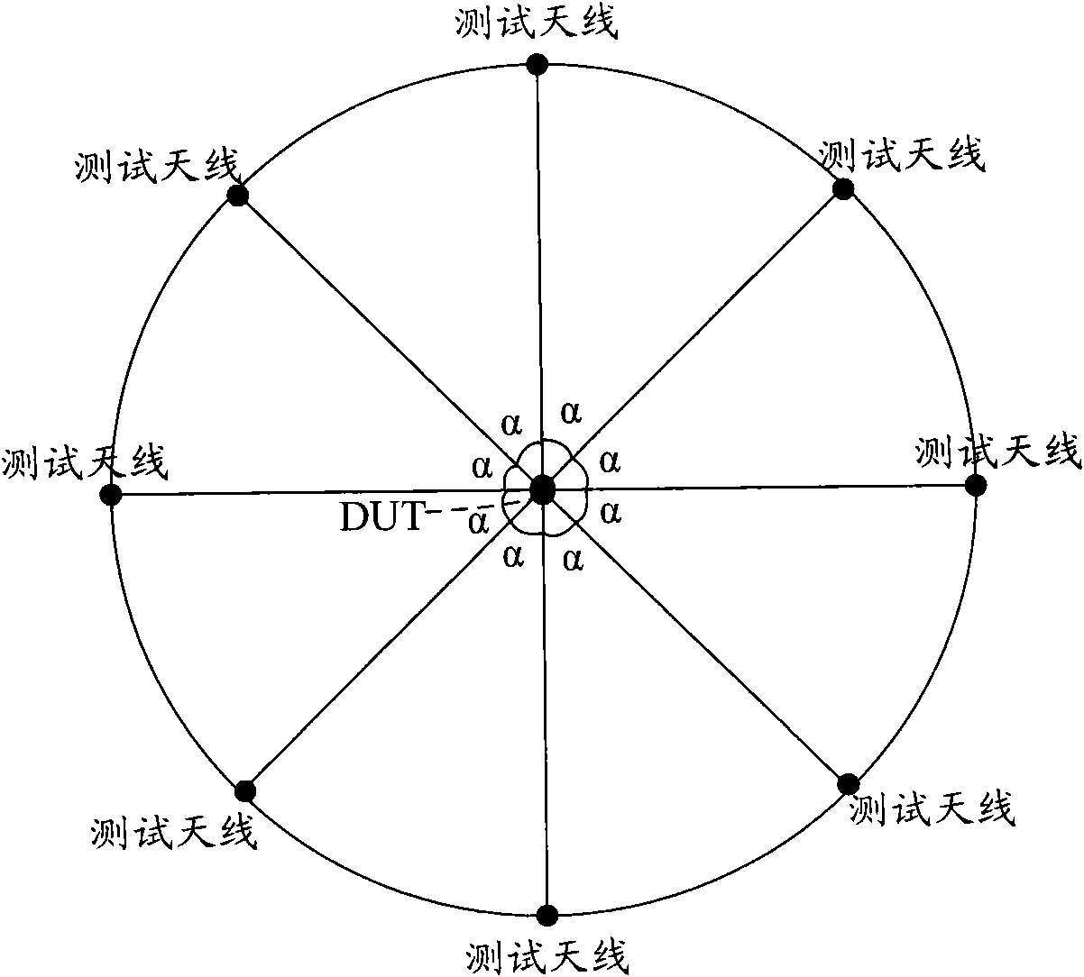
[0039] In order to realize the space performance test and evaluation of the multi-antenna terminal, the embodiment of the present invention provides a test environment based on a channel simulator and an anechoic chamber (also called a full-wave absorption anechoic chamber), which can meet the requirements of MIMOOTA. Among them, there are a certain number of test antennas in the anechoic chamber, and these test antennas are located in different positions in the anechoic chamber, and send signals with certain time and space characteristics to test the multi-antenna terminal; the device under test (DUT, Device Under Test) is located in the center of the anechoic chamber, and each test antenna is located on a circle centered on the DUT, which is to ensure that the signals sent by each test antenna reach the DUT at the s...


PUM


Abstract

The invention discloses a system for testing a multi-antenna terminal, comprising a base station simulator, a channel simulator, a mapping module and a soundproofing darkroom, wherein the soundproofing darkroom is internally provided with a device under test (DUT) and N test antennas; the base station simulator is used for outputting m paths of emission signals to the channel simulator; the channel simulator is used for adopting a channel model to simulate so as to obtain n paths of signals and outputting the n paths of signals to the mapping module in accordance with the received m paths of emission signals; the mapping module is used for mapping the received n paths of signals to the n test antennas in the soundproofing darkroom for air emission; and the DUT is used for receiving signals from the air and processing the received signals so as to finish the over the air (OTA) test. The invention also discloses a method for testing the multi-antenna terminal. By using the method and system disclosed by the invention, the OTA test and estimation for the multi-antenna terminal can be realized.

Description

technical field [0001] The invention relates to the technical field of radio frequency testing of wireless communication equipment, in particular to a testing method and system for a multi-antenna terminal. Background technique [0002] With the development of modern industry, all kinds of wireless communication equipment can only guarantee the communication quality if they have good transmitting and receiving performance, that is, the total radiated power (TRP, Total Radiated Power) needs to be higher than a certain limit, and the total radiated sensitivity (TRS, Total Radiated Sensitivity) needs to be lower than a certain limit, that is to say, the space radio frequency performance (OTA, Over The Air) test index is required to be good. [0003] In order to ensure the normal use of the mobile terminal equipment in the network, the Cellular Telecommunications Industry Association (CTIA, Cellular Telecommunications Industry Association) has formulated a test standard for the ...

Claims


Application Information

Patent Timeline
Patent Type & Authority Applications(China)
IPC IPC(8): H04M1/24H04B7/02
CPCH04W8/245H04W24/06
Inventor 郭阳郑欣宇禹忠
Owner ZTE CORP
Why Eureka
Try Eureka