Heating system for treating a fibrous material web

A heating system and web technology, applied in the direction of textiles and papermaking, paper machines, dryers, etc., can solve the problems of high consumption of cooling water, and achieve the effect of reducing cooling water consumption, reducing energy costs, and reducing consumption

Inactive Publication Date: 2011-08-10
VOITH PATENT GMBH
View PDF3 Cites 7 Cited by
  • Summary
  • Abstract
  • Description
  • Claims
  • Application Information

AI Technical Summary

Problems solved by technology

resulting in a relatively high consumption of cooling water

Method used


Image

  • Heating system for treating a fibrous material web
  • Heating system for treating a fibrous material web
  • Heating system for treating a fibrous material web

Examples


Embodiment Construction

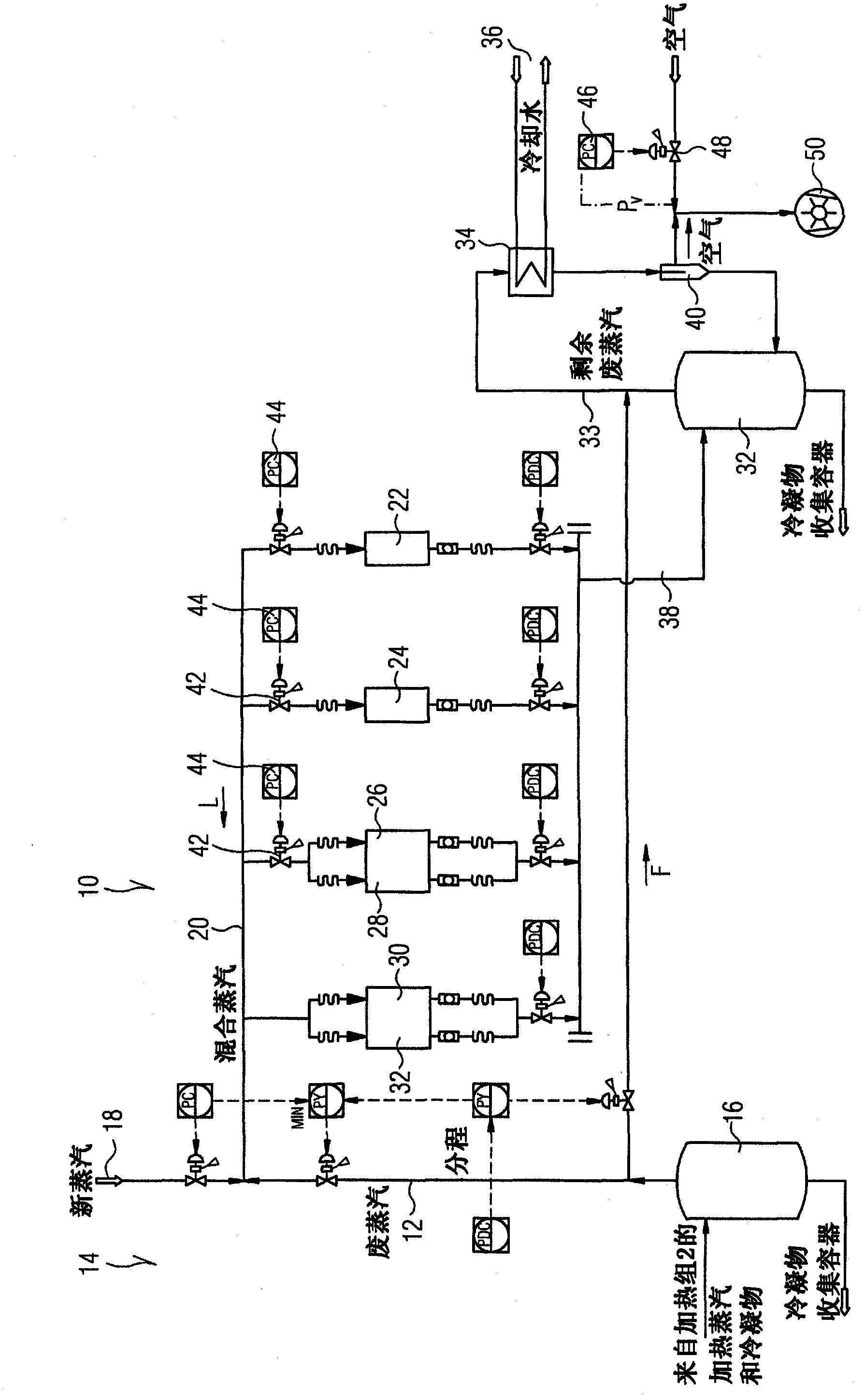
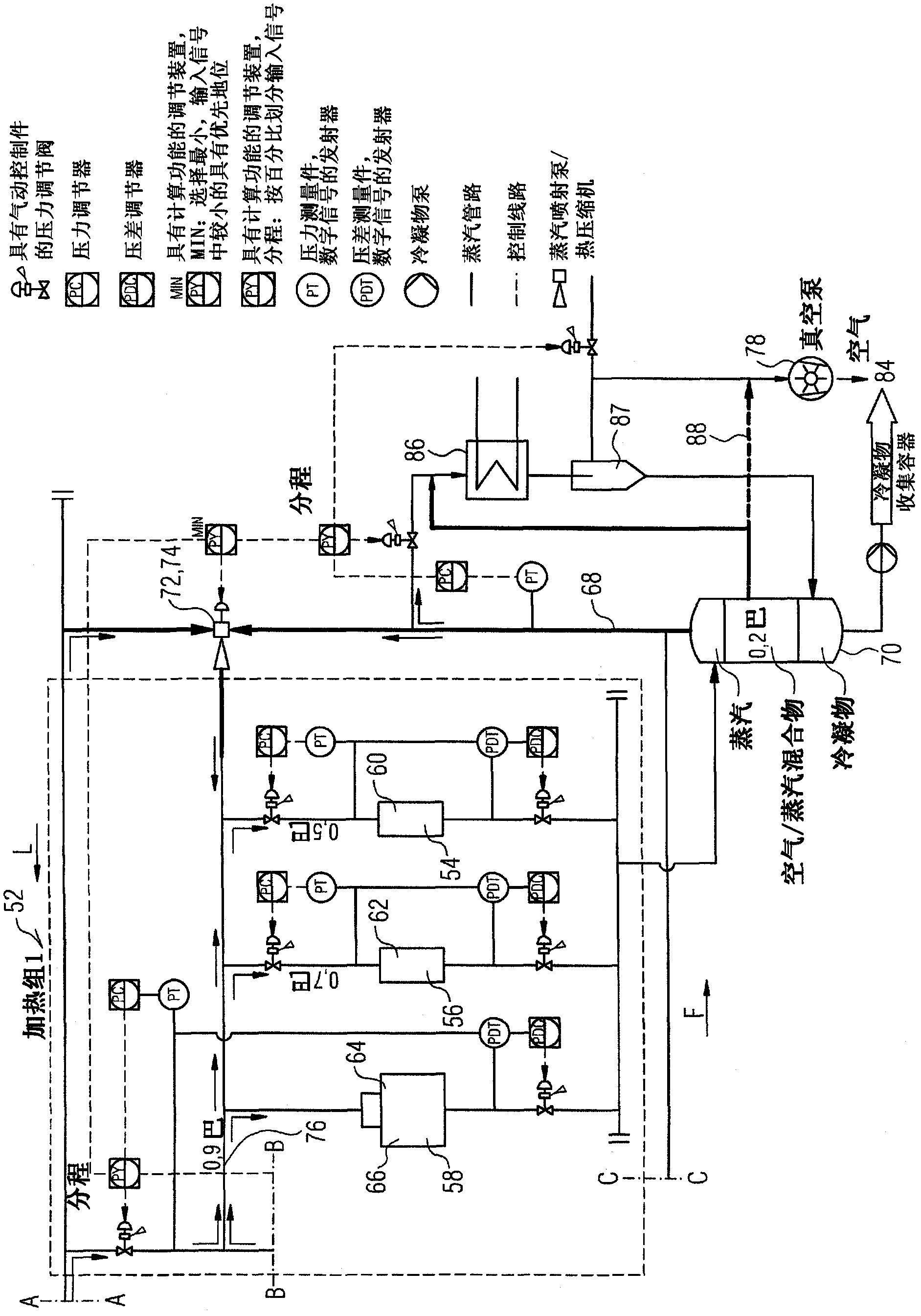
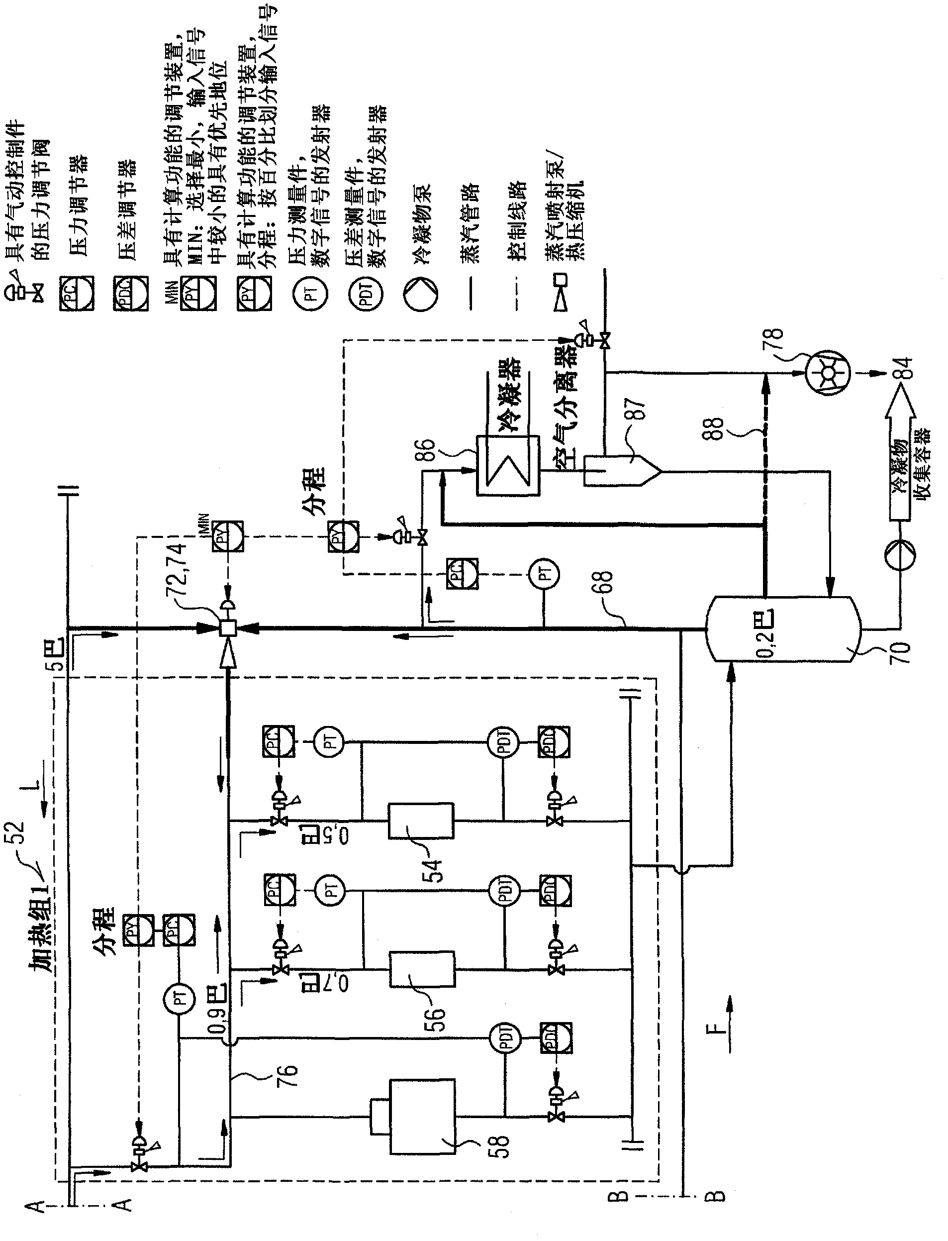
[0035] figure 2The first heating group 52 viewed in the direction of web travel L of an exemplary embodiment of the heating system according to the invention is shown in a simplified schematic diagram. The heating system is used, for example, for treating fibrous webs, especially paper, cardboard or tissue webs, and comprises one or more heating groups, each comprising one or more heating stages , the heating stages each comprise one or more drying cylinders heated with steam.

[0036] If according to figure 2 It can be seen that the first heating group 52 comprises, for example, three heating stages 54-58. In this case, the two first heating stages 54 , 56 each include, for example, only one drying cylinder 60 or 62 , while the third heating stage 58 here includes, for example, two drying cylinders 64 and 66 .

[0037] Means are provided for compressing the residual waste steam 68 remaining after the last heating stage or heating group 52 of the heating system seen along...


PUM


Abstract

Means (72, 74) are provided in a heating system for treating a fibrous material web, particularly a paper, cardboard, or tissue web, comprising one or more heating groups, each having one or more heating levels (54-58), which include one or more drying cylinders (60-66, 80) heated by steam, in order to compress the residual exhaust vapor remaining after the last heating level or group of the heating system as viewed in the flow direction of the steam, and to return the same to the heating system.

Description

technical field [0001] The invention relates to a heating system for treating fibrous webs, in particular paper, cardboard or tissue webs, the heating system having one or more heating groups, the heating The groups each comprise one or more heating stages each comprising one or more drying cylinders heated with steam. The invention also relates to a machine for the production and / or treatment of fibrous webs, in particular paper, cardboard or tissue webs, which machine has one or more drying sections , each of the drying sections includes one or more such heating systems. Background technique [0002] One or more heating systems of this type can be assigned, for example, to the drying section of a paper machine and / or a coating machine. figure 1 The first heating group 10 of a conventional heating system, seen in the direction of web travel L, is shown schematically. Here, the waste steam 12 emerges from a second heating stage or heating group 14 seen in the direction of...

Claims


Application Information

Patent Timeline
Patent Type & Authority Applications(China)
IPC IPC(8): D21F5/02D21F5/04D21F5/20
CPCD21F5/20D21F5/04D21F5/028
Inventor 马丁・道纳
Owner VOITH PATENT GMBH
Why Eureka
Try Eureka