Laminating machine
A technology of laminating machine and motion mechanism, applied in lamination device, lamination auxiliary operation, lamination, etc., to avoid air bubbles and improve yield rate
- Summary
- Abstract
- Description
- Claims
- Application Information
AI Technical Summary
Problems solved by technology
Method used
Image

Examples
Embodiment Construction
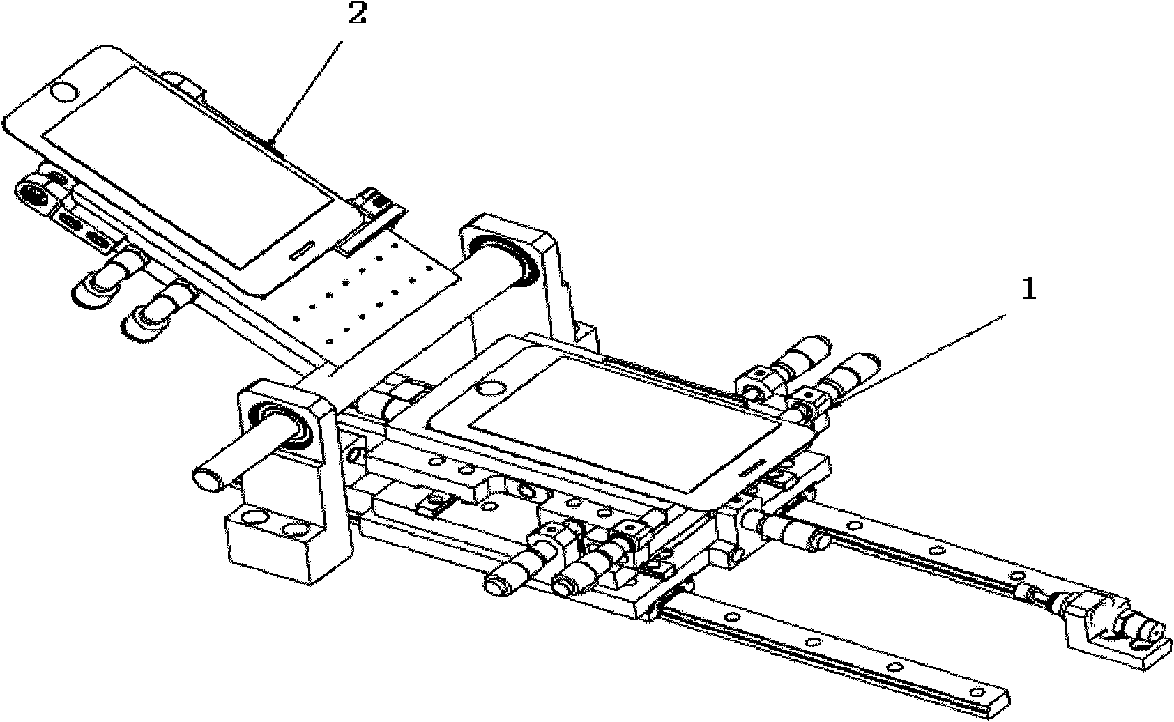
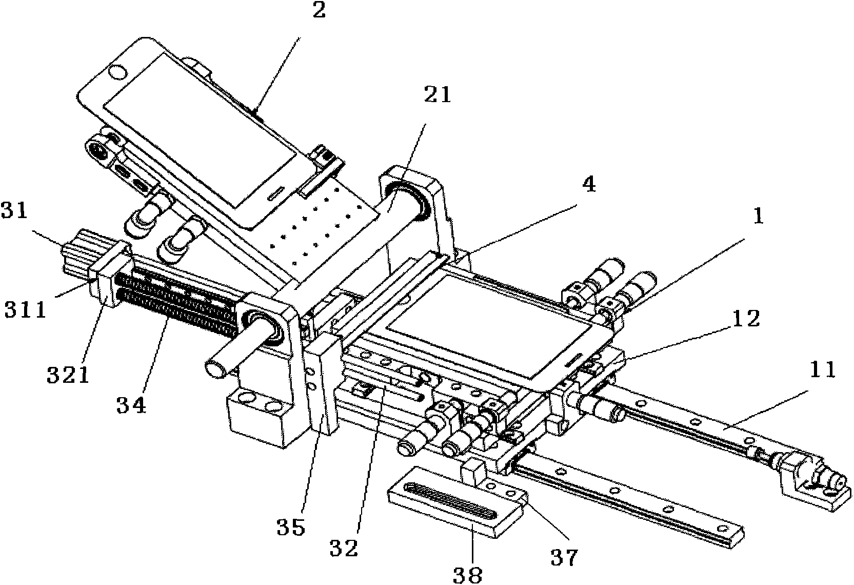
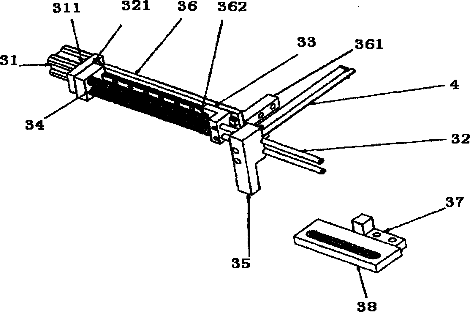
[0013] First give a preferred embodiment and describe the present invention in detail as follows in conjunction with the drawings: the laminating machine of the present invention mainly includes a machine platform, a lower suction platform 1, an upper suction platform 2, and an isolation device. Figure 2 ~ Figure 4 ,in:
[0014] The machine platform is not shown in the figure. Two parallel linear guide rails 11 are installed on the machine platform. A flat plate 12 that can slide forward and backward along the linear guide rail 11 is installed on the linear guide rail 11. The lower suction platform 1 is fixedly installed on the On the flat plate 12, it can move back and forth along with the movement of the flat plate 12 under the action of external forces such as cylinders along the linear guide rail 11; a vacuum device is arranged on the lower suction platform 1, which can make the work on the lower suction platform 1 At the same time, vacuum adsorption is carried out for th...
PUM
 Abstract
Description
Claims
Application Information