Method and device for increasing sucking capability and distance of suction opening

A technology of suction capacity and suction port, which is applied in pump devices, liquid variable capacity machinery, machines/engines, etc., can solve the problems of small fresh air shielding capacity, weak jet rotation strength, and reduced suction efficiency, and achieves the scope of application. Wide, strong suction ability, improve the effect of suction ability and distance

Inactive Publication Date: 2011-08-17
颜正 +1
6 Cites 0 Cited by

AI-Extracted Technical Summary

Problems solved by technology

[0002] In engineering fields such as ventilation and dust removal, harmful gas emission, etc., suction is inseparable, that is, the use of fans to capture harmful substances first, and then centralized treatment. But so far, the problem of how to improve the suction capacity and distance of the suction port It has been bothering various production departments and relevant sci...

Method used

Blower fan 1B and exhaust pipe 1A form suction system; Blower fan 3, stationary bellows 4, rotary seal 5, rotary annular air duct 6, rotary bellows 7, jet nozzle 8, rotary bearing 9 and motor 10, turbine The speed reducer 11 and the gear reduction transmission mechanism 12 form a rotating jet generation system. When the device is working, the air blower 3 generates positive pressure air, which passes through the stationary bellows 4 and the rotating annular air duct 6 to reach the rotating bellows 7 . Since the static bellows 4 and the rotating annular air duct 6 are connected by the rotating seal 5, the leakage of the positive press...

Abstract

The invention discloses a method for increasing the sucking capability and distance of a suction opening. The periphery of the suction opening is provided with a plurality of efflux nozzles which are driven to rotate around the suction opening by a power source and can spray efflux. By adopting the method, the sucking capability and distance of the suction opening can be greatly increased. The method can be widely applied to the engineering fields of ventilation, dust removal and emission of harmful gas. The invention also provides a device for increasing the sucking capability and distance of the suction opening.

Application Domain

Pump installationsPositive-displacement liquid engines

Technology Topic

EngineeringNozzle

Image

  • Method and device for increasing sucking capability and distance of suction opening
  • Method and device for increasing sucking capability and distance of suction opening
  • Method and device for increasing sucking capability and distance of suction opening

Examples

  • Experimental program(1)

Example Embodiment

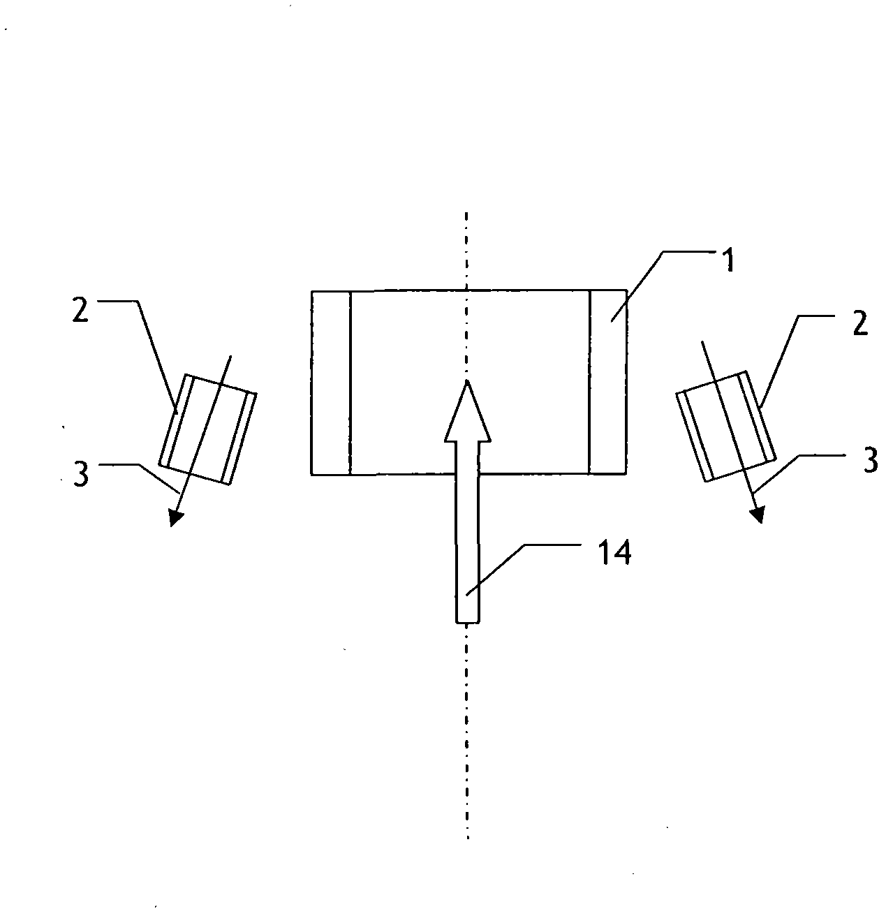
[0015] figure 1 It is a schematic diagram of the principle of the method of the present invention. See figure 1 The method of the present invention to improve the suction capacity and distance of the suction port is to set a number of jet nozzles 2 around the suction port that are driven by a power source and rotate around the suction port, and the jet nozzle axis is inclined to the suction port axis. The jet is a gas flow (or steam or a gas-liquid mixture).
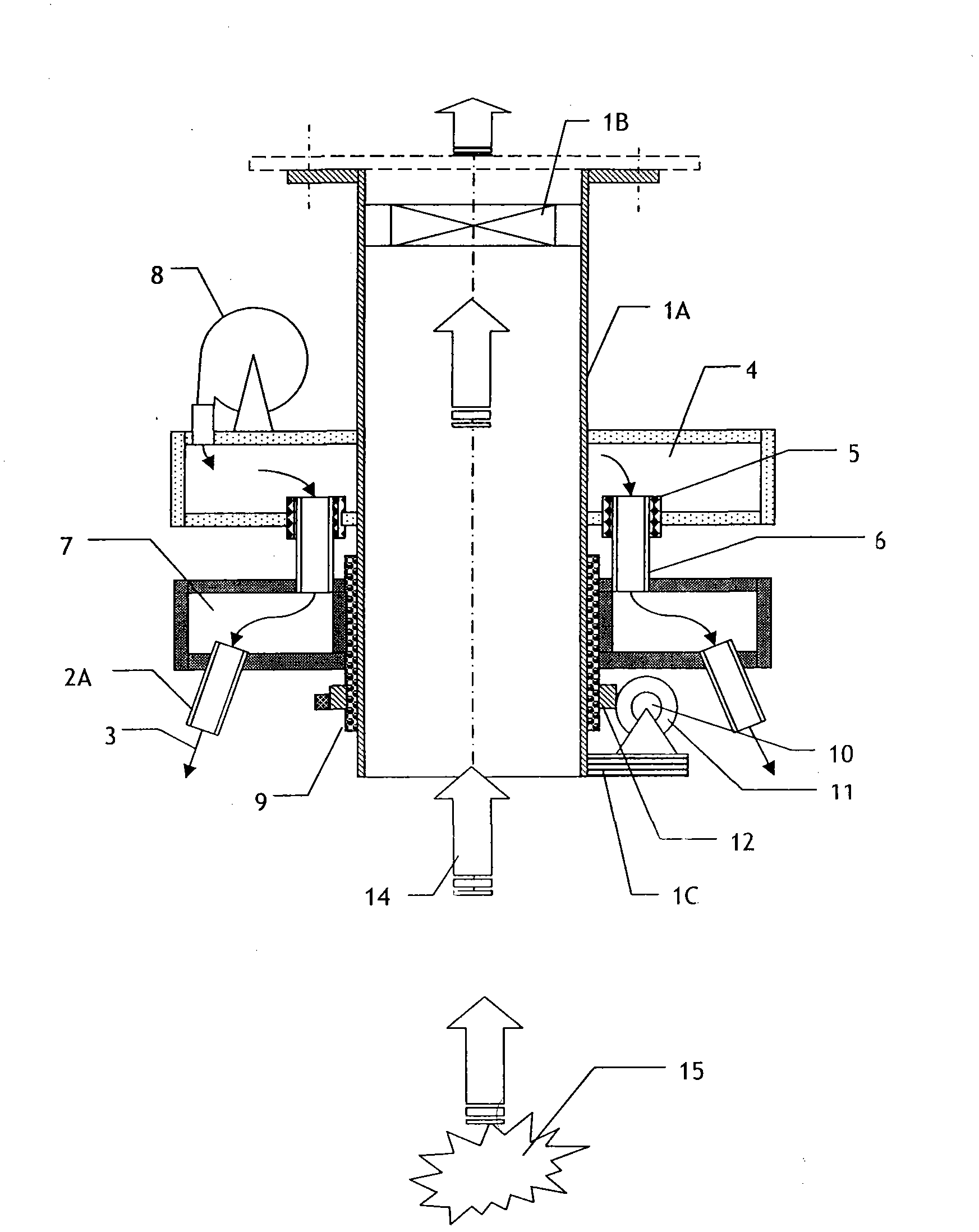
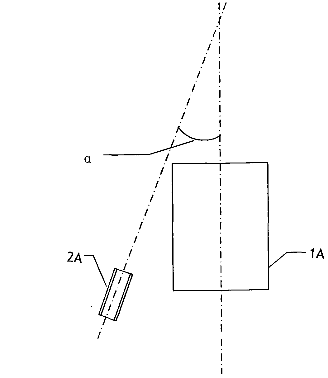
[0016] figure 2 , image 3 It is a schematic diagram of the device structure of the present invention. See Figure 2 ~ Figure 3 The device of the present invention includes an exhaust pipe 1A, an exhaust fan 1B installed at the outlet of the exhaust pipe, which is installed on the outer periphery of the exhaust pipe in turn, is installed in the exhaust pipe through an outsourcing rotary bearing 9 and a gear reduction transmission mechanism 12 and a turbo reducer 11 The rotating wind box 7 and the stationary wind box 4 driven by the motor 10 on the air duct motor seat 1C. A number of jet nozzles 2 are arranged on the rotating wind box along the outer periphery of the exhaust pipe, and a number of rotating annular air pipes 6 corresponding to the jet nozzles respectively. One end of each rotating annular wind pipe extends into the static wind box and a rotating seal 5 is installed between the wall of the static wind box. The air blowing port of the blower 3 installed on the static wind box extends into the static wind box. The angle α between the jet nozzle axis and the exhaust fan axis is 30° (see image 3 ), the radial included angle β is 15° (see Figure 4 ).
[0017] The exhaust fan 1B and the exhaust pipe 1A constitute the suction system; the blower 3, the stationary wind box 4, the rotating seal 5, the rotating annular duct 6, the rotating wind box 7, the jet nozzle 8, the rotating bearing 9 and the motor 10, the turbo reducer 11 The gear reduction transmission mechanism 12 constitutes a rotating jet generating system. When the device is working, the blower 3 generates positive pressure air, which passes through the stationary wind box 4 and the rotating annular wind pipe 6 to the rotating wind box 7. Since the stationary wind box 4 and the rotating annular air duct 6 are connected by the rotating seal 5, the positive pressure air leakage is reduced, and the rotating annular air duct 6 is ensured to rotate along the axial direction of the suction duct 1A. After the positive pressure air reaches the rotating wind box 7, it is ejected outward through the jet nozzle 2. The rotating wind box 7 and the jet nozzle 2 are driven by a drive system composed of a motor 10, a turbine reducer 11, and a gear reduction transmission mechanism 12 to rotate along the axial direction of the exhaust pipe, thereby generating a strong rotating airflow. Under the action of the rotating airflow, the suction system of the suction system can greatly enhance the suction capacity of harmful dust.
[0018] In the above device, the motor 10, the exhaust fan 1B and the blower 3 all adopt frequency conversion speed regulation, and the operating parameters such as the nozzle rotation speed, the exhaust air volume, and the air blowing volume are controlled by the frequency conversion regulator.
[0019] figure 1 , figure 2 The serial numbers 3, 14, and 15 respectively indicate the direction of jet, the direction of inhalation, and harmful dust.
[0020] The above-mentioned embodiments are for further explanation of the above-mentioned content of the present invention, but it should not be understood that the scope of the above-mentioned subject of the present invention is limited to the above-mentioned embodiments. All technologies implemented based on the above content belong to the scope of the present invention.

PUM

PropertyMeasurementUnit
Angle15.0 ~ 30.0deg
Radial angle0.0 ~ 30.0deg

Description & Claims & Application Information

We can also present the details of the Description, Claims and Application information to help users get a comprehensive understanding of the technical details of the patent, such as background art, summary of invention, brief description of drawings, description of embodiments, and other original content. On the other hand, users can also determine the specific scope of protection of the technology through the list of claims; as well as understand the changes in the life cycle of the technology with the presentation of the patent timeline. Login to view more.

Similar technology patents

Method for improving polluted soil

ActiveCN1689721AThe harmless effect is stable for a long timeWide range of applications
Owner:阿斯特古东京股份有限公司 +3

Classification and recommendation of technical efficacy words

Why Eureka
Try Eureka