LED (light emitting diode) pluggable pipe

A technology for plugging and unplugging tubes and light source components is applied in the cooling/heating device, lighting device, light source and other directions of lighting devices, which can solve the problems of LED lamps and lanterns, such as heat dissipation, performance, electrical stability, waste mercury pollution, etc.

Inactive Publication Date: 2011-08-17
福建雨露光电科技有限公司
View PDF0 Cites 6 Cited by
  • Summary
  • Abstract
  • Description
  • Claims
  • Application Information

AI Technical Summary

Problems solved by technology

[0002] LED is a green light source. Compared with incandescent lamps and fluorescent lamps, it not only has high power saving efficiency, but also has no pollution to the environment. However, how to solve the heat dissipation problem of LED lamps is an important technical bottleneck affecting its performance.
[0003] Although traditional standard energy-saving lamps are energy-saving to a certain extent compared with incandescent lamps, they have problems such as short life, fragile, and difficult transportation, especially their waste will produce mercury pollution
The existing LED energy-saving lamps on the market generally include light source components, radiators, electrical boxes, and corresponding electrical connections, installation structures, etc., which solve the shortcomings of traditional energy-saving lamps to a certain extent, but because all light sources are in the same radiator or the light source and radiator are covered in a light-transmitting cover, which makes the heat emitted by the LED light source difficult to dissipate, affecting the service life of the LED, and at the same time, the heat emitted by the LED also affects the stability of the electrical appliance
And most of the LED energy-saving lamps on the market, the LED light source particles are exposed, there is no protection for the LED particles, it is easy to damage, and the glare is very large, which cannot be a good substitute for traditional energy-saving lamps.

Method used


Image

  • LED (light emitting diode) pluggable pipe
  • LED (light emitting diode) pluggable pipe
  • LED (light emitting diode) pluggable pipe

Examples


Embodiment Construction

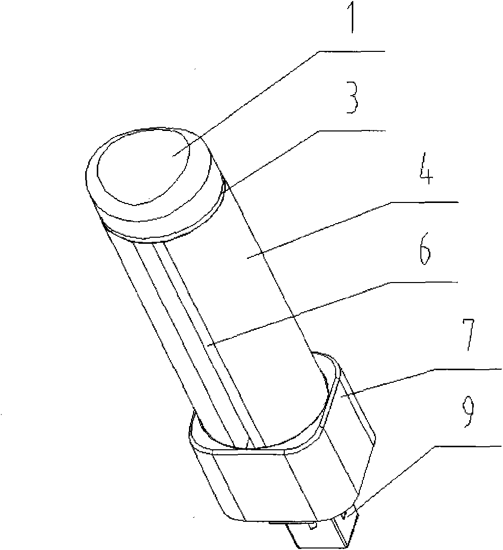
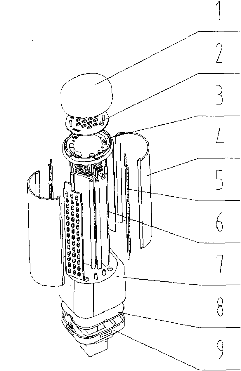
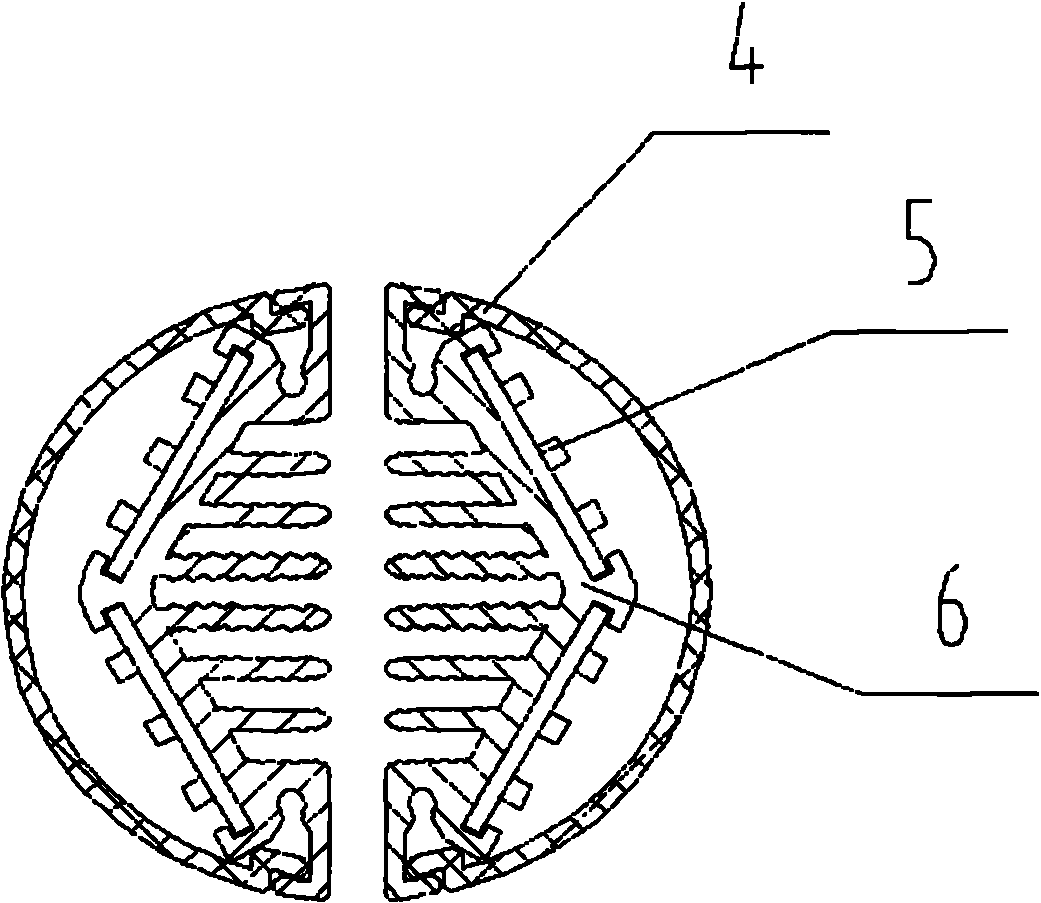
[0017] This embodiment is 11W. The top light transmission cover (1), the top light source assembly (2), and the top light source assembly mounting part (3) form an elliptical light source module. The side light transmission cover (4), the side light source assembly (5 ), heat dissipation profiles (6) to form a bar-shaped light source module, the present embodiment uses three bar-shaped light source modules plus the top elliptical light source module, and each bar-shaped light source module is provided with two The side light source assembly (5) is pasted on the "V"-shaped heat dissipation profile (6). Each side light source assembly (5) uses 84 pieces of 0.06W LED light sources, which are welded on the aluminum substrate, and the back of the aluminum substrate is coated with heat-conducting silicone grease Attached to the radiator, there is a ventilation gap between the radiators to effectively dissipate heat.

[0018] The above is only a preferred embodiment of an LED plug-in...


PUM


Abstract

The invention discloses a structure of an LED (light emitting diode) pluggable pipe and relates to the technical field of semiconductor illumination. The LED pluggable pipe provided by the invention is composed of a top light-transmittable shade, a top light source assembly, a top light source assembly mounting piece, a side light-transmittable shade, a side light source assembly, a heat radiating sectional material, a lamp body plastic piece, a driving assembly and a lamp head plastic piece. According to the design application of the LED pluggable pipe, through manufacturing the section of the heat radiating sectional material into a V-shaped structure, the light emitted from light source modules is overlapped, no dark region is formed, light are emitted uniformly, and the illumination uniformity in an effective illumination range is improved; moreover, compared with similar products, the LED pluggable pipe has obvious effects of small volume, light weight, less heat productivity, high light emitting efficiency, long service life and energy conservation.

Description

technical field [0001] The invention discloses a structure of an LED plug-in tube with good uniform light emission and good heat dissipation effect, and relates to the technical field of semiconductor lighting. Background technique [0002] LED is a green light source. Compared with incandescent lamps and fluorescent lamps, it not only has high power saving efficiency, but also has no pollution to the environment. However, how to solve the heat dissipation problem of LED lamps is an important technical bottleneck affecting its performance. [0003] Although traditional standard energy-saving lamps are energy-saving to a certain extent compared with incandescent lamps, they have problems such as short life, fragile, and difficult to transport, especially their waste will produce mercury pollution. The existing LED energy-saving lamps on the market generally include light source components, radiators, electrical boxes, and corresponding electrical connections, installation str...

Claims


Application Information

Patent Timeline
Patent Type & Authority Applications(China)
IPC IPC(8): F21V29/00F21V3/04F21V25/12F21Y101/02F21V29/85F21Y107/00F21Y115/10
Inventor 马强冉大全王加华张林刚陈荣
Owner 福建雨露光电科技有限公司
Why Eureka
Try Eureka