
Optical detection device and detection method

A technology of optical detection and detection device, which is applied in the field of optical detection, can solve the problem that the collimator cannot generate a target with a limited distance, and achieve the effect of a reliable measuring instrument

Active Publication Date: 2011-08-17
云南大景光电科技有限公司
View PDF4 Cites 42 Cited by
  • Summary
  • Abstract
  • Description
  • Claims
  • Application Information

AI Technical Summary

Problems solved by technology

[0005] The problem with existing measuring devices is that the collimator cannot generate a finitely distant target

Method used


Image

  • Optical detection device and detection method
  • Optical detection device and detection method
  • Optical detection device and detection method

Examples


Embodiment Construction

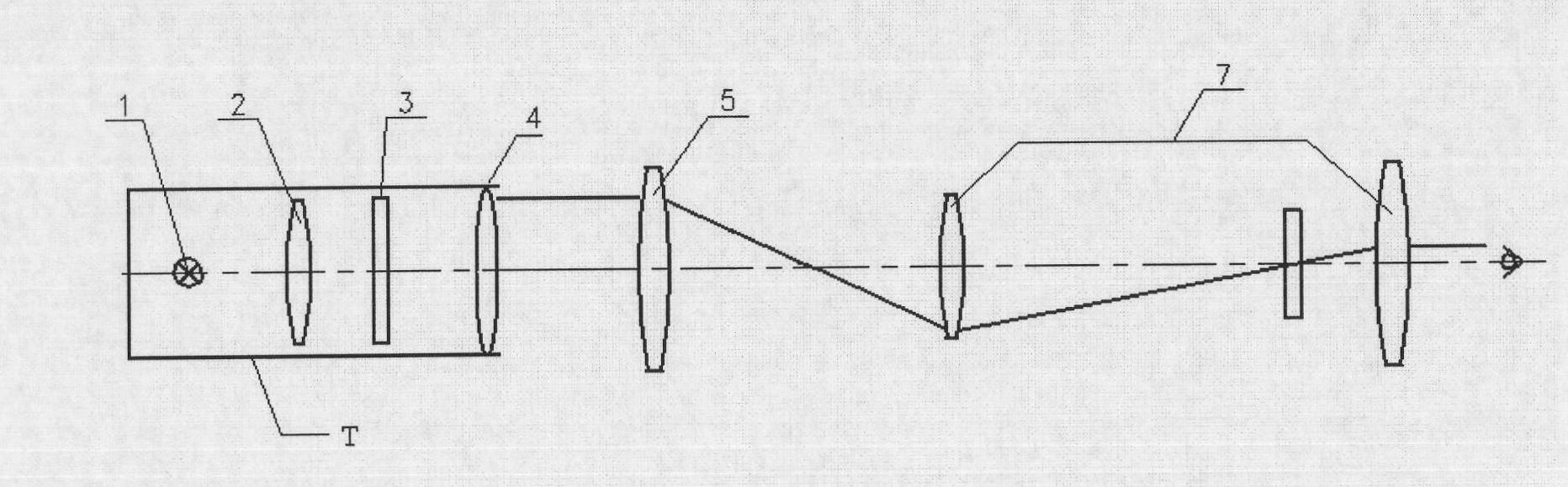
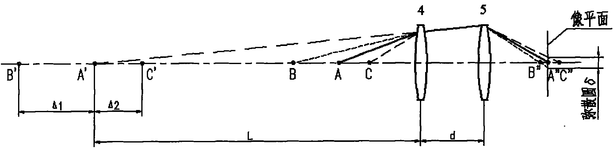
[0033] like Figure 4 As shown, the depth of field detection device of the present invention is composed of guide rail group g1, illuminator group g2, resolution plate group g3, collimator mirror group g4, lens mount group g5, measuring microscope group g6, and slide seat group g7. The guide rail group g1 is the base of the detection device, on which are set the resolution plate group g3 and the collimator mirror group g4, the resolution board group g3 can move relative to the collimator mirror group g4, the resolution board group g3 and the collimator mirror group g4 It is used to generate the imaging target of the inspected lens, that is, an object formed at a limited distance from the inspected lens. A measuring microscope group g6 is installed on the guide rail group, and the measuring microscope is used to perform resolution detection on the inspected lens. A lens mount group g5 is arranged between the collimating lens group g4 and the measuring microscope group g6, and ...


PUM


Abstract

The invention discloses an optical detection device and an optical detection method. The detection method detects the field depth by using a method for detecting resolution, and the difference of nearest and farthest object plane positions where the permissive spatial frequency values can be just distinguished is used as the field depth of a lens. The detection device comprises a guide rail set, an illumination apparatus set, a resolution plate set, a collimating lens set, a lens seat set, a measurement microscope set and a sliding seat set. The measurement microscope is used for detecting the resolution of the detected lens; and the sliding seat set is used for axially moving the collimating lens set, the lens seat set and the measurement microscope set to adjust the distance between a resolution plate and a collimating lens so as to generate a finitely far object, the object distance of which can be changed. By using the field depth detection device, the field depth index of the lens can be quantified, and a measurement instrument is provided for researching a big field depth lens.

Description

technical field [0001] The invention relates to the field of optical detection, in particular to a depth of field detection device and a depth of field detection method. Background technique [0002] Camera setups have long suffered from insufficient depth of field. Depth of field refers to the object distance range measured along the axis of the imager in front of the camera lens or other imager to obtain a clear image. At present, the depth of field is obtained through theoretical calculation, and there is no equipment available for detection. However, the theoretical calculation value is only an ideal situation, and it often deviates from the actual situation. Therefore, there is an urgent need for an instrument that can detect the specific value of the depth of field to quantitatively compare the depth of field levels of different lenses, and provide a basis for the research and development of large depth of field lenses. Reliable measuring instrument. [0003] Depth ...

Claims


Application Information

Patent Timeline
Patent Type & Authority Applications(China)
IPC IPC(8): G01M11/02
Inventor 郭京左珊魏育五张晓杰郭佳李明秋石金贵
Owner 云南大景光电科技有限公司
Features
  • Generate Ideas
  • Intellectual Property
  • Life Sciences
  • Materials
  • Tech Scout
  • Unparalleled Data Quality
  • Higher Quality Content
  • 60% Fewer Hallucinations
Learn More