Monitoring system and method based on vibration sensor array
A vibration sensor and monitoring system technology, which is applied in the directions of instruments, anti-theft alarm mechanical start-ups, and measuring devices, can solve problems such as high cost, impact, and unknown damage to leaking cables, and achieve low cost, convenient layout, and difficult detection and discovery. Effect
- Summary
- Abstract
- Description
- Claims
- Application Information
AI Technical Summary
Problems solved by technology
Method used
Image
Examples
Embodiment 1
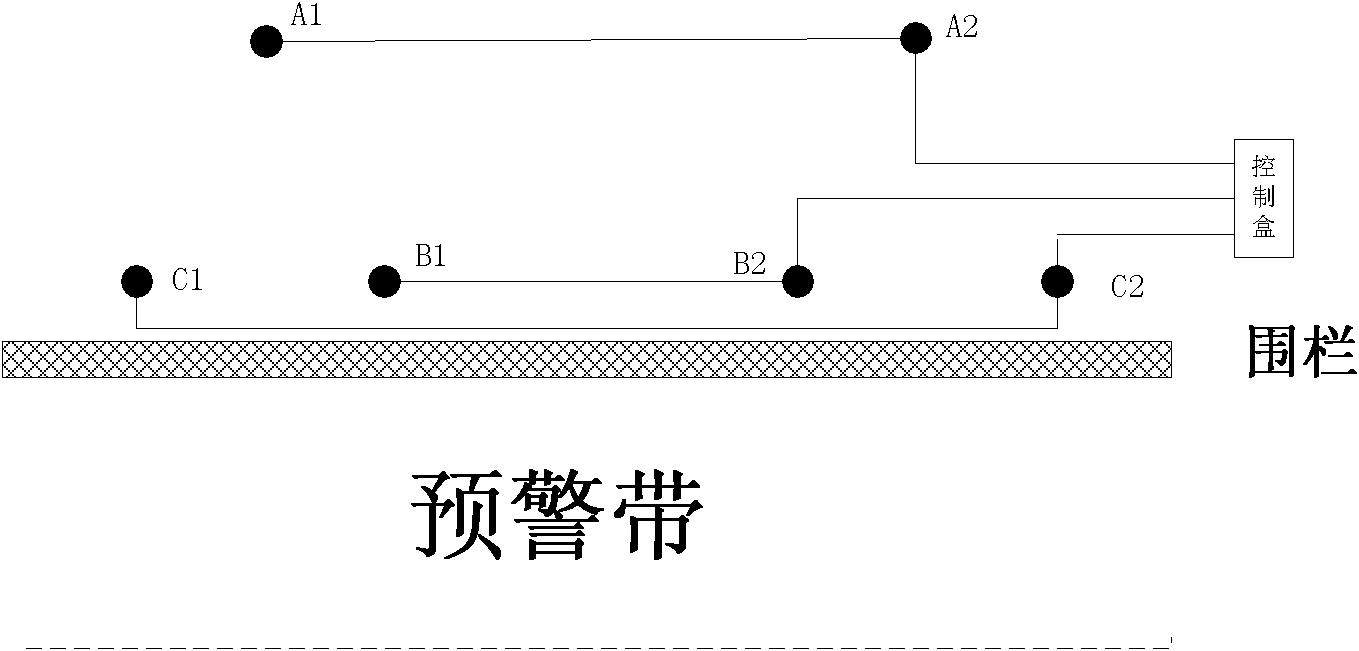
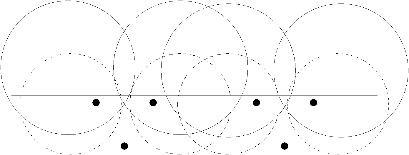
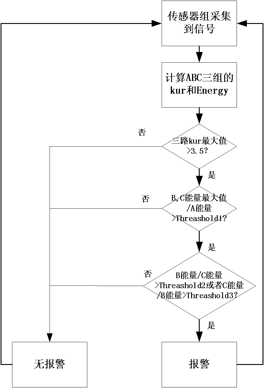
[0033] Such as figure 1 and 3 The one-sided three-way single-layer early warning belt shown in the figure, the vibration sensors are divided into A, B, and C three-way, each sensor has two vibration sensors connected in series, the layout scheme is shown in the figure. And A, B, C three-way sensors are all arranged in the fence. The principle of the scheme is based on the vibration signal energy received by the sensor. A.Energy, B.Energy and C.Energy are used to represent the vibration signal energy received by the three groups of sensors A, B, and C respectively. According to relevant literature, the vibration signal energy and The transmission distance is inversely proportional, and the energy source whose ratio of energy received by two shock sensors is a certain value is on a circular trajectory, such as figure 2 shown. According to this principle, a detection algorithm can be designed to detect whether an intruder has passed through the virtual fence. The early warni...
Embodiment 2
[0046] Such as Figure 4 and 5 In the asymmetrical four-way single-layer early warning belt shown, the two roads B and C are arranged in the early warning belt, and the two road sensors A and D are arranged on both sides of the early warning belt. The early warning method is as follows:
[0047] 1. The sensor group collects the signal and transmits it to the controller for processing;
[0048] 2. Calculate A, B, C, D three-way energy A.Energy, B.Energy, C.Energy, D.Energy and kurtosis A.kur, B.kur, C.kur, D.kur;
[0049] 3. The maximum value of the kurtosis of A, B, C, and D is greater than 3.5, otherwise go to 8;
[0050] 4. The maximum energy value of the B and C roads divided by the D road energy is greater than Threashold1, otherwise go to 8;
[0051] 5. The energy of road B and C divided by the energy of road A is greater than Threashold2, otherwise go to 8;
[0052] 6. Alarm;
[0053] 7. Return 1;
[0054] 8. Do not call the police, go to 7.
[0055] Among them, Th...
Embodiment 3
[0057] Such as Figure 6 and 7 In the shown asymmetrical three-way single-layer early warning belt, two roads B are arranged in the early warning belt, and two road sensors A and C are arranged on both sides of the early warning belt. The early warning method is as follows:
[0058] 1. The sensor group collects the signal and transmits it to the controller for processing;
[0059] 2. Calculate A, B, C three-way energy A.Energy, B.Energy, C.Energy and kurtosis A.kur, B.kur, C.kur;
[0060] 3. The maximum value of the kurtosis of A, B, and C is greater than 3.5, otherwise go to 8;
[0061] 4. The energy of channel B divided by the energy of channel C is greater than Threashold1, otherwise go to 8;
[0062] 5. The energy of channel B divided by the energy of channel A is greater than Threashold2, otherwise go to 8;
[0063] 6. Alarm;
[0064] 7. Return 1;
[0065] 8. Do not call the police, go to 7.
[0066] Among them, Threashold1 is the multiple of road B greater than r...
PUM
 Abstract
Description
Claims
Application Information
 - R&D
- Intellectual Property
- Life Sciences
- Materials
- Tech Scout
- Unparalleled Data Quality
- Higher Quality Content
- 60% Fewer Hallucinations
Browse by: Latest US Patents, China's latest patents, Technical Efficacy Thesaurus, Application Domain, Technology Topic, Popular Technical Reports.
© 2025 PatSnap. All rights reserved.Legal|Privacy policy|Modern Slavery Act Transparency Statement|Sitemap|About US| Contact US: help@patsnap.com


