Air curtain design method for sealing transmission channel in laser

A technology of transmission channel and design method, applied in lasers, laser parts, electrical components, etc., can solve problems such as difficulty in obtaining technical details, achieve stable flow field conditions, increase sealing performance, and avoid waste.

Inactive Publication Date: 2012-05-30
INST OF OPTICS & ELECTRONICS - CHINESE ACAD OF SCI
View PDF0 Cites 0 Cited by
  • Summary
  • Abstract
  • Description
  • Claims
  • Application Information

AI Technical Summary

Problems solved by technology

Although a lot of research on air curtains has been done abroad, due to special reasons, it is difficult to obtain relevant technical details in China

Method used


Image

  • Air curtain design method for sealing transmission channel in laser
  • Air curtain design method for sealing transmission channel in laser
  • Air curtain design method for sealing transmission channel in laser

Examples


Embodiment 1

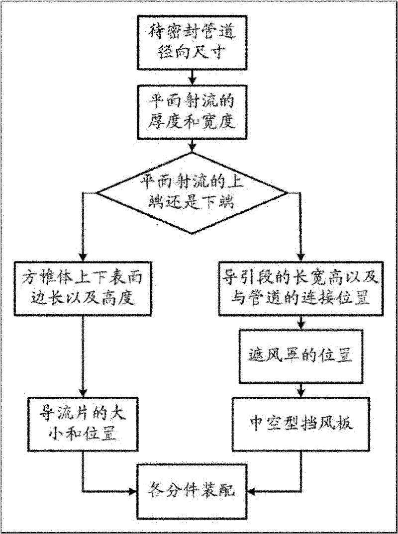
[0038] The specific steps are as figure 1 Shown:

[0039] (1) Structural modeling

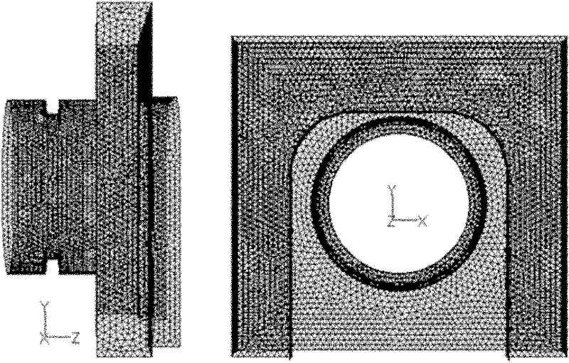
[0040] The first step is to determine the thickness b=L / 4=30mm of the plane jet tube according to the diameter L=120mm of the inner transmission channel of the laser. The width of the plane jet tube is taken as: d=1.83*L=220mm.

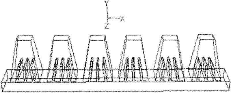
[0041] The second step is to establish a square cone structure, considering matching with the existing gas supply pipeline. The side length of the upper surface is taken as 14mm, the side length of the lower surface is taken as 28mm, and the height is taken as 40mm.

[0042] The third step is to place three deflectors in the square cone. The thickness of the deflector is 1mm, the height is 20mm, the distance between the deflectors is 7mm, and the inclination angle of the deflectors on both sides is θ=arctan(0.16) .

[0043] In the fourth step, the number of square cones is taken as n=6, and the distance between the square cones is 7 mm, and the square cones are place...

Embodiment 2

[0055] The specific steps are as figure 1 Shown:

[0056] (1) Structural modeling

[0057] In the first step, it is first assumed that the diameter of the laser inner transmission channel is L=180mm, and thus the thickness of the plane jet tube is determined as b=L / 4=45mm. The width of the plane jet tube is taken as: d=1.8*L≈330mm.

[0058] The second step is to establish a square pyramid structure. The side length of the upper surface is taken as 21mm, the side length of the lower surface is taken as 42mm, and the height is taken as 60mm.

[0059] The third step is to place three deflectors in the square cone. The thickness of the deflector is 1.5mm, the height is 30mm, the distance between the deflectors is 10.5mm, and the inclination angle of the deflectors on both sides is θ≈arctan( 0.16).

[0060] In the fourth step, the number of square cones is taken as n=6, and the distance between the square cones is 10.5mm, and the square cones are placed symmetrically and evenly...


PUM


Abstract

The invention relates to an air curtain design method for sealing a transmission channel in laser, which comprises the following steps: (1) determining the dimensions of a plane jet forming section according to the diameter of the transmission channel in the laser, wherein the dimensions mainly refer to the thickness and width of a plane jet; (2) after determining the dimensions of the plane jet forming section, determining the side length and height of the upper and lower surfaces of a pyramid; (3) in order to guarantee the uniformity of the air velocity, placing a flow deflector in the pyramid; (4) setting the length, width and height of an air curtain guide section and the connecting position of the transmission channel in the laser; (5) in order to decrease the thickness of boundary layers in different gas mixing regions and reduce the optical path difference because of gas density fluctuation, arranging a windshield cover at one side on which the air curtain guide section is connected with the outside; and (6) placing a hollow windshield plate in the transmission channel in the laser, wherein the position of the hollow windshield plate can be set according to the width of a turbulence mixing region. The air curtain design method provided by the invention can maintain the single uniform gas with a low absorption coefficient in the transmission channel in the laser, avoids the introduction of the larger optical path difference and has the characteristics of high laser transmissivity and high temperature resistance.

Description

technical field [0001] The invention belongs to the field of laser inner channel transmission, and relates to an air curtain design method for sealing the laser inner channel. Background technique [0002] When a high-power-density laser beam is transmitted in a gas medium, a small part of the laser energy will be absorbed by molecules and particles in the gas, and the absorbed laser energy will heat the gas, resulting in a decrease in the gas density in a local area, thereby changing the refractive index of the gas , the change of the refractive index affects the transmission of the laser in the gas and reduces the energy concentration reaching the far field. Especially, in the inner channel, the diameter of the laser beam is generally relatively small, the power density of the laser is relatively high, and the heating effect of the laser is very obvious. [0003] In order to weaken the thermal effect of the gas in the inner channel, people have proposed a method of inject...

Claims


Application Information

Patent Timeline
Patent Type & Authority Patents(China)
IPC IPC(8): H01S3/034
Inventor 孙运强习锋杰陈洪斌刘顺发王继红向春生许晓军陆启生
Owner INST OF OPTICS & ELECTRONICS - CHINESE ACAD OF SCI
Why Eureka
Try Eureka