Non-isolated resonant converter

一种谐振变换器、非隔离式的技术,应用在仪器、直流功率输入变换为直流功率输出、调节电变量等方向

Active Publication Date: 2011-08-17
JIANGXI POWERLAND ENERGY SCI-TECH CO LTD
View PDF12 Cites 34 Cited by
  • Summary
  • Abstract
  • Description
  • Claims
  • Application Information

AI Technical Summary

Problems solved by technology

[0010] However, it is precisely because of the characteristic that the autotransformer uses one winding, it has its particularity compared with the isolated transformer in practical applications, so that the autotransformer cannot directly replace the isolated transformer to form a resonant converter. Based on this consideration, we are committed to the development of resonant converters composed of autotransformers to reduce volume and loss. This case arose from this

Method used


Image

  • Non-isolated resonant converter
  • Non-isolated resonant converter
  • Non-isolated resonant converter

Examples


Embodiment Construction

[0050] The structure and beneficial effects of the present invention will be described in detail below in conjunction with the accompanying drawings.

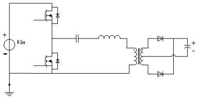
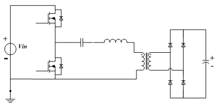
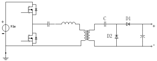
[0051] first reference Figure 21 As shown, the present invention provides a non-isolated resonant converter, which mainly includes three parts: a switching circuit, a resonant circuit and a rectifying and filtering circuit. These three parts are connected in sequence, and for the resonant circuit, an autotransformer is included and the capacitance and inductance respectively connected to the autotransformer; it should be noted that the capacitance and inductance contained in the resonant circuit here only refer to the type of its components, not only one capacitance and one inductance, that is, It is possible for this resonant circuit to have multiple capacitors and inductors connected, but only of the type.

[0052] first reference Figure 4 As shown, it is the first implementation structure provided by the present inventio...


PUM


Abstract

The invention discloses a non-isolated resonant converter. The non-isolated resonant converter comprises a switching circuit, a resonant circuit and a rectifier filter circuit which are connected in turn, wherein the resonant circuit comprises an auto-transformer, and a capacitor and an inductor which are connected with the auto-transformer respectively. The transformer has a small volume, low loss and high power density.

Description

technical field [0001] The invention belongs to the field of electric energy conversion, and in particular relates to a non-isolated resonant converter applied to photovoltaic inverters, LED constant current drives and multi-channel constant current drives. Background technique [0002] High frequency, high efficiency and high power density are the development trend of switching power supplies. Resonant converters have become a research hotspot in the field of power conversion technology due to their soft switching characteristics and good EMI performance. [0003] The current common resonant converters are all based on isolated transformers, which can be used with reference Figure 1 to Figure 3 As shown, all of them are resonant half-bridge converters connected by isolation transformers. Among them, figure 1 and figure 2 The output of the resonant converter shown uses a full-wave rectification circuit, while image 3 The output of the transformer uses a half-wave volta...

Claims


Application Information

Patent Timeline
Patent Type & Authority Applications(China)
IPC IPC(8): H02M3/338
CPCY02B70/1425Y02B70/1491Y02B70/1433H02M3/338H02M3/33569H02M3/158H02M2001/0058Y02B70/10H02M1/0058H02M3/01
Inventor 徐明李新磊
Owner JIANGXI POWERLAND ENERGY SCI-TECH CO LTD
Why Eureka
Try Eureka