Multiple-motor control circuit with link arm bridge

A technology of multiple motors and control circuits, which is applied in the direction of controlling multiple DC motors, etc., to achieve the effect of reducing cost and volume and improving reliability

Inactive Publication Date: 2011-08-17
广东戈兰玛汽车系统有限公司
View PDF4 Cites 11 Cited by
  • Summary
  • Abstract
  • Description
  • Claims
  • Application Information

AI Technical Summary

Problems solved by technology

In order to achieve the application requirements of forward and reverse rotation in two different directions and different rotation speeds, usually each motor needs a bridge circuit to control its forward, reverse and speed regulation, and multiple motors require multiple bridge circuits. Circuit to control and make the control system costly and the control circuit bulky

Method used


Image

  • Multiple-motor control circuit with link arm bridge
  • Multiple-motor control circuit with link arm bridge
  • Multiple-motor control circuit with link arm bridge

Examples


Embodiment 1

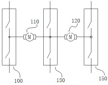
[0017] figure 1 It is a block diagram of multi-motor control circuit with link bridge driving 2 motors.

[0018] The half-bridge switching drive circuit 100 is composed of two electronic switches. These two electronic switches can select the appropriate electronic device according to the voltage, power, PWM frequency required by the application. One end of the bridge arm is connected to the positive power supply, and each bridge arm can share the same power supply. The other end of the bridge arm is connected to ground or a negative supply. Other bridge arms are similar. When the DC motor 110 is required to run, the half-bridge switching drive circuit 100 and the half-bridge switching drive circuit 130 are combined to form a bridge circuit to control its rotation direction and speed, and the half-bridge switching drive circuit 150 is turned off at the same time. When the DC motor 120 is required to run, the half-bridge switching drive circuit 100 and the half-bridge switc...

Embodiment 2

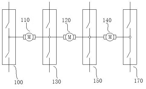
[0020] figure 2 It is a block diagram of multi-motor control circuit with link bridge driving 3 motors.

[0021] The figure includes a half-bridge switching drive circuit 100 ; a half-bridge switching drive circuit 130 ; a half-bridge switching drive circuit 150 ; a brushed DC motor 110 ; a brushed DC motor 120 ; and a brushed DC motor 140 . When the DC motor 110 is required to run, the half-bridge switch drive circuit 100 and the half-bridge switch drive circuit 130 are combined to form a bridge circuit to control its rotation direction and speed, and at the same time, other half-bridge switch drive circuits are turned off. When the DC motor 120 is required to run, the half-bridge switch drive circuit 100 and the half-bridge switch drive circuit 150 are combined to form a bridge circuit to control its rotation direction and speed, and the other half-bridge switch drive circuits 130 are turned off at the same time. When the DC motor 140 is required to run, the half-bridge sw...


PUM


Abstract

The invention provides a multiple-motor control circuit with a link arm bridge, comprising a half-bridge switch mode drive circuit. The control circuit is characterized in that the half-bridge circuit 100 and the half-bridge circuit 130 among a half-bridge circuit 100, a half-bridge circuit 130 and a half-bridge circuit 150 are combined to control the rotation direction and revolving speed of any direct current (DC) motor 110 so as to form the multiple-motor control circuit with a link arm-bridge; when the multiple motors are required to be controlled for operation, arm bridges can be added to realize the purpose; and every time one arm bridge is added, at least one motor can be controlled additionally. The control circuit provided by the invention drives a plurality of DC motors, thus realizing that a simple control device is utilized to control the plurality of DC motors. The control circuit provided by the invention is used for controlling the plurality of DC motors, thus greatly reducing the construction cost and volume of a control system and improving the reliability of the system. The control circuit is suitable for controlling multiple DC motors.

Description

technical field [0001] The invention relates to a multi-motor control circuit of a bridge with connected arms, which belongs to the technical field of DC motor control. Background technique [0002] Brushed DC motors are used in a wide variety of industrial, agricultural, commercial and home appliances. Brushed DC motors are used to drive other mechanisms to convert electrical energy and mechanical energy to generate motion. In order to achieve the application requirements of forward and reverse rotation in two different directions and different rotation speeds, usually each motor needs a bridge circuit to control its forward, reverse and speed regulation, and multiple motors require multiple bridge circuits. The circuit is used to control the cost of the control system and the control circuit is bulky. The present invention only uses a circuit with a link bridge to control two DC motors. This saves 50 percent in cost and control board space. Due to the reduction of co...

Claims


Application Information

Patent Timeline
Patent Type & Authority Applications(China)
IPC IPC(8): H02P5/68
Inventor 张志辉
Owner 广东戈兰玛汽车系统有限公司
Why Eureka
Try Eureka