Method and system for determining transmission parameter values between node equipment as well as node equipment
A technology of transmission parameters and node equipment, which is applied in the field of information storage and can solve the problems of unreasonable signal integrity of transmission signal parameter settings.
- Summary
- Abstract
- Description
- Claims
- Application Information
AI Technical Summary
Problems solved by technology
Method used
Image
Examples
Embodiment 1
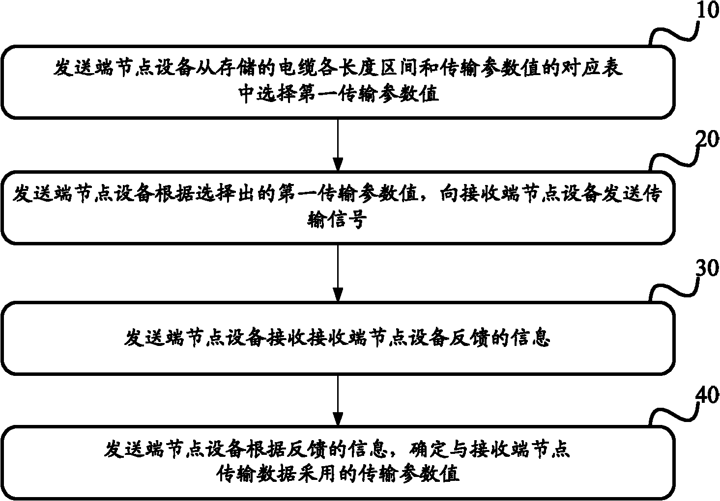
[0067] A corresponding table of cable length intervals and transmission parameter values is stored in the sending end node device or in the shared storage space in the storage system that can be accessed by the node devices in the storage system, and the corresponding table includes at least two cable length intervals, and the Transmission parameter values corresponding to at least two cable length intervals. The information in the correspondence table can be obtained in the following ways:
[0068] The cable length supported by the storage system is divided into at least two length intervals. In this embodiment, the cable length range is divided into three cable length intervals, which are [0 meter, 0.5 meter], [0.5 meter, 5 meter], [5 meters, 8 meters]. How to divide the length interval can be obtained according to the test experience, and it is not unique. For example, the cable length range from 0m to 8m can also be divided into two cables: [0m, 3m] and [3m, 8m]. len...
Embodiment 2
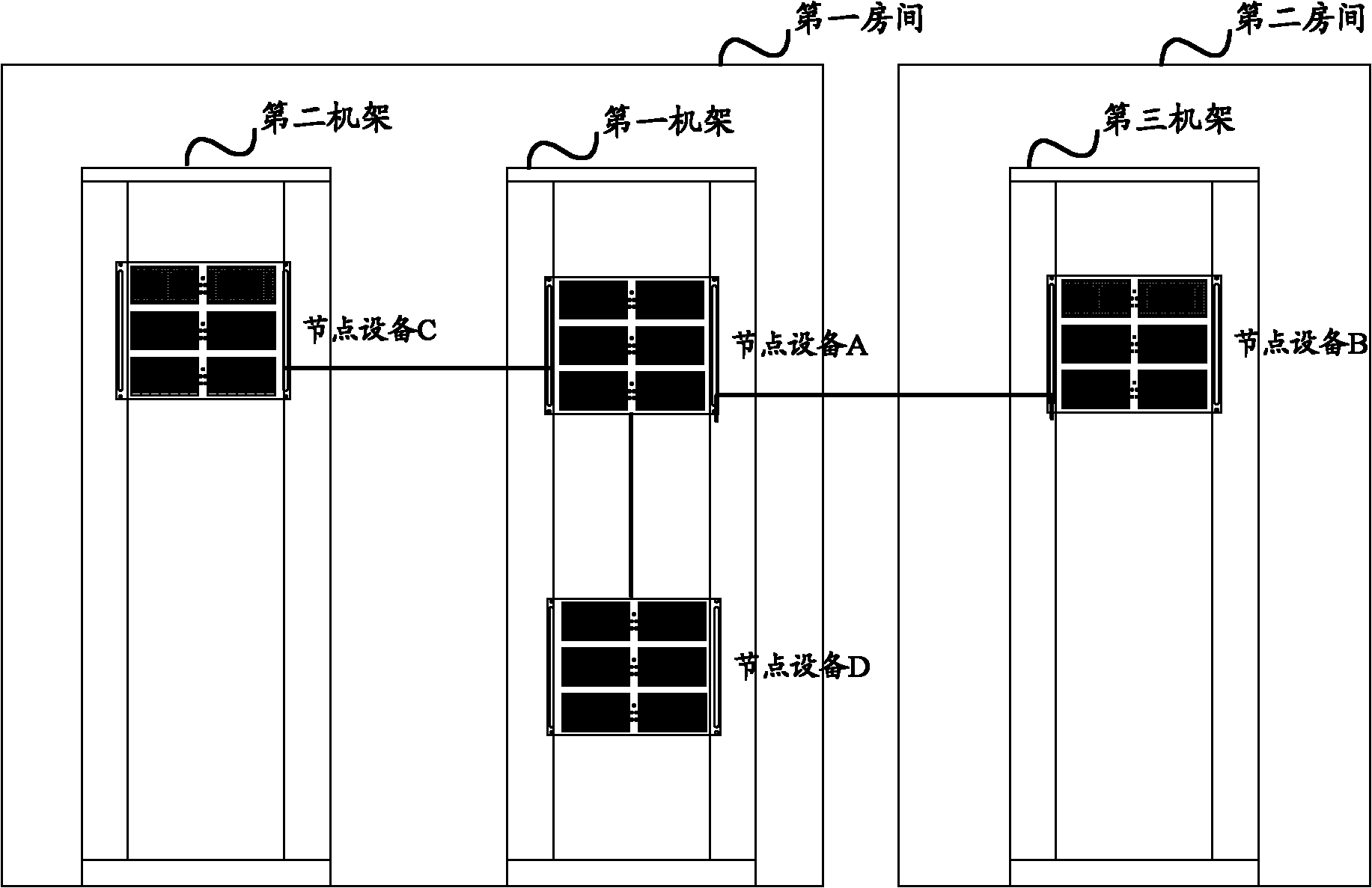
[0081] attached figure 2 It is a schematic diagram of a storage system applied to the scheme for determining transmission parameter values provided by the embodiment of the present invention, and the storage system includes node device A, node device B, node device C, and node device D. In this embodiment, the cable length range supported by the storage system is 0 meters to 8 meters as an example for introduction. It should be noted that the cable length ranges supported by different storage systems are different. Among them, the distance between node equipment A and node equipment B is relatively far, and they are respectively placed in hardware racks in different rooms and connected by an 8-meter-long cable; node equipment A and node equipment C are respectively placed in different racks in the same room , are connected through a 3-meter-long cable; node device A and node device D are placed in the same rack in the same room, and the distance is relatively close, and the...
Embodiment 3
[0108] attached Figure 4 It is a schematic flow chart of an embodiment of the present invention, and this embodiment is attached figure 2 Node device A is the sending end node device, node device C is the receiving end node device, node device A and node device C are respectively placed in different racks in the same room, and connected by a 3-meter-long cable.
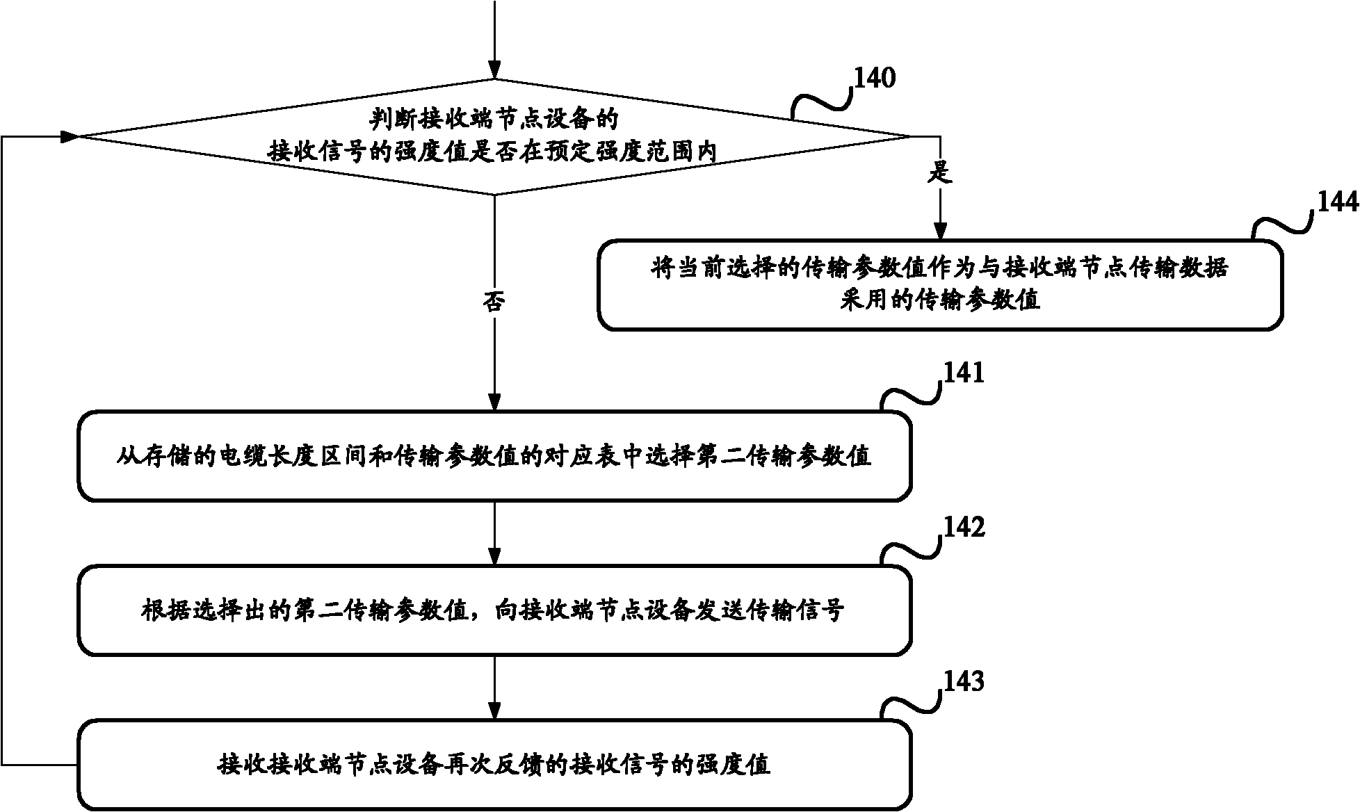
[0109] Step 401, node device A determines the transmission parameter value adopted by node device C to transmit data, and selects the transmission parameter corresponding to the length interval with the longest cable length from the stored transmission parameter values corresponding to each length interval as shown in Table 3 value, that is, the transmission parameter value corresponding to the length interval [5 meters, 8 meters] is 1111;
[0110] Step 402, node device A sends a transmission signal with an intensity value of 1200MV to node device C according to the selected transmission parameter value 1111;
...
PUM
 Abstract
Description
Claims
Application Information
 - R&D
- Intellectual Property
- Life Sciences
- Materials
- Tech Scout
- Unparalleled Data Quality
- Higher Quality Content
- 60% Fewer Hallucinations
Browse by: Latest US Patents, China's latest patents, Technical Efficacy Thesaurus, Application Domain, Technology Topic, Popular Technical Reports.
© 2025 PatSnap. All rights reserved.Legal|Privacy policy|Modern Slavery Act Transparency Statement|Sitemap|About US| Contact US: help@patsnap.com


