Electrosurgical hf generator

A high-frequency generator, electrosurgery technology, used in heating surgical instruments, medical science, parts of surgical instruments, etc., can solve problems such as tissue overheating and tissue damage

Inactive Publication Date: 2011-08-17
ERBE ELEKTROMEDIZIN GMBH
View PDF3 Cites 10 Cited by
  • Summary
  • Abstract
  • Description
  • Claims
  • Application Information

AI Technical Summary

Problems solved by technology

The disadvantage is that the high-frequency current also flows through untreated tissue to the neutral electrode
In particular, if the cross-sectional area

Method used


Image

  • Electrosurgical hf generator
  • Electrosurgical hf generator
  • Electrosurgical hf generator

Examples


Embodiment Construction

[0019] In the following description, the same reference numerals are used to denote the same components and components having the same functions.

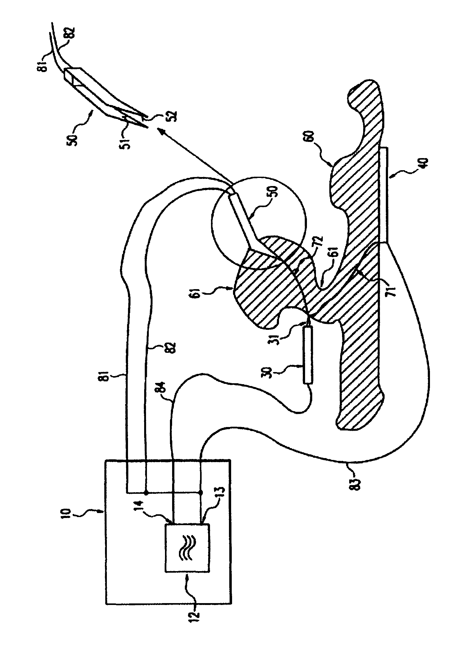
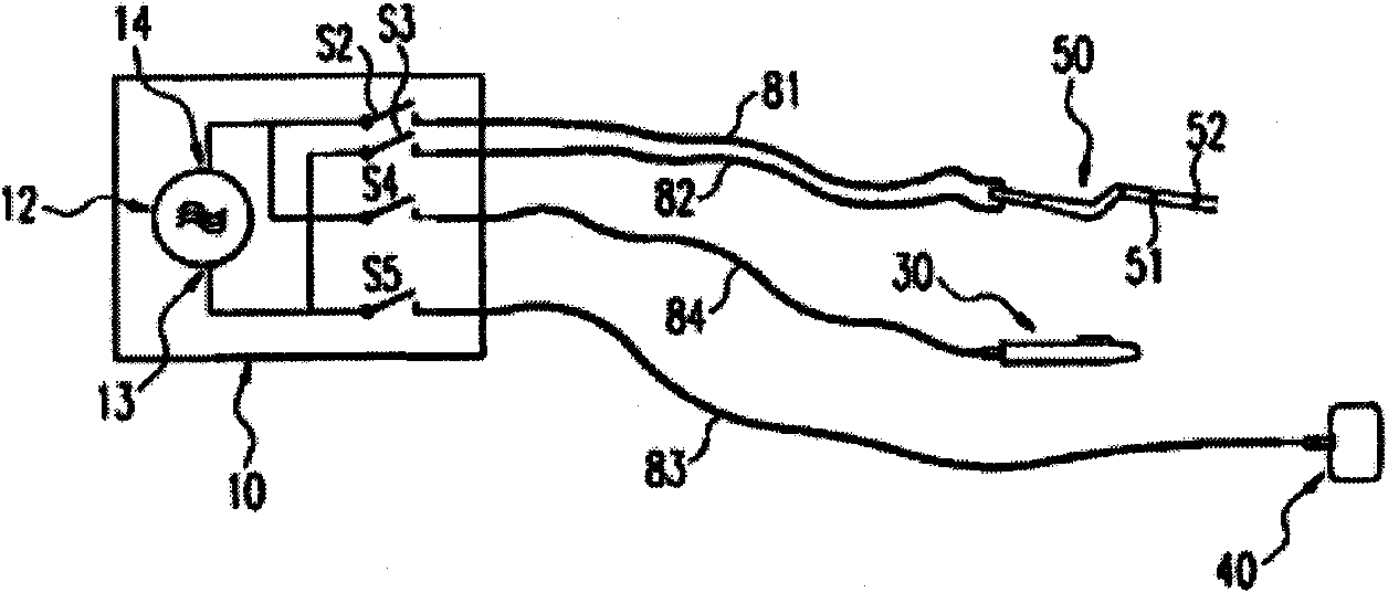
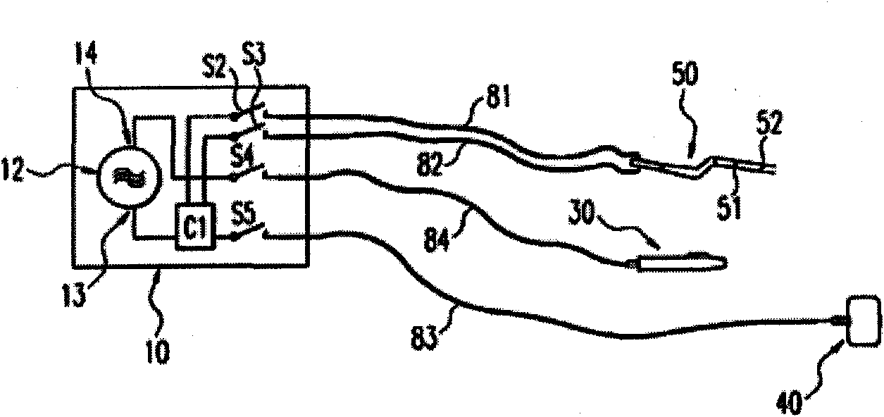
[0020] like figure 1 The high-frequency generator 10 shown comprises a generator circuit 12 with a neutral output 13 and an active output 14 . The neutral output 13 is connected via a wire 83 to a neutral electrode 40 which contacts a large area of ​​tissue 60 . In addition, the neutral output terminal 13 is connected via wires 81, 82 to two clamping surfaces 51, 52 of a pair of bipolar forceps 50, which clamping surfaces 51, 52 serve as auxiliary neutral electrodes and are in contact with the tissue 60. Part 61 to be separated. The active output 14 is connected via a wire 84 to an active electrode 30 configured as a handpiece and comprising an electrode terminal 31 . Via a switch (not shown in the figure, which can be configured as a foot switch or a hand switch located on the active electrode 30), the surgeon can close the cir...


PUM


Abstract

The invention relates to cutting or coagulating biological tissue using an electrosurgical HF generator (10) comprising a generator circuit (12) exciting an HF current between an active electrode (30) and at least one neutral electrode (40), wherein undesired tissue heating due to the HF current can be reduced if the electrosurgical HF generator (10) comprises at least one further auxiliary neutral electrode (50, 51, 52) connected in parallel to the neutral electrode (40).

Description

technical field [0001] The invention relates to an electrosurgical high-frequency generator according to the preamble of claim 1 . Background technique [0002] Electrosurgical high-frequency generators are used for treating physiological tissue, in particular for cutting or coagulating physiological tissue. To this end, a generator circuit is used to generate a high-frequency current which flows between an active electrode and at least one neutral electrode via a first current path through the tissue. Thus, the generator circuit includes an active output and a neutral output. [0003] In high-frequency surgery, a distinction is made between so-called monopolar and multipolar applications. In monopolar applications, the active electrode is configured as an insulated handpiece, eg, having an electrode tip that is directed by the surgeon to the tissue region to be treated. A high frequency current is passed through the body tissue to a neutral electrode which contacts a lar...

Claims


Application Information

Patent Timeline
IPC IPC(8): A61B18/12A61B18/16A61B18/14
CPCA61B18/16A61B18/1442A61B18/1206A61B2018/124A61B2018/165
Inventor J·贝勒R·克莱因
Owner ERBE ELEKTROMEDIZIN GMBH
Why Eureka
Try Eureka