
Clutch device for electronic lock
A clutch device, electronic lock technology, applied in building locks, non-mechanical drive-operated locks, door/window accessories, etc., can solve problems such as difficult maintenance, troublesome production and installation processes, and many parts and components
- Summary
- Abstract
- Description
- Claims
- Application Information
AI Technical Summary
Problems solved by technology
Method used
Image

Examples
Embodiment Construction
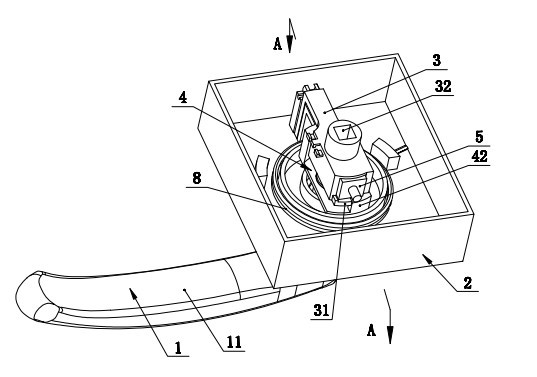
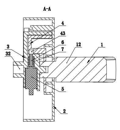
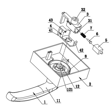
[0012] Such as figure 1 , 2 , 3 shows a clutch device of an electronic lock, including a handle 1, a handle panel 2, an upper clutch 3, a lower clutch 4, an electromagnet 5, a clutch pin 6, and a clutch pin return spring 7, wherein the The handle 1 includes a handle 11 and a handle rotating column 12, the handle 11 is arranged on the outside of the handle panel 2, and the handle rotating column 12 passes through the handle panel 2 and the lower clutch 4 in the handle panel 2. Matching, the lower clutch 4 is sleeved on the handle rotating column 12, and the upper circumference of the end of the handle rotating column 12 is evenly distributed with several opening grooves 121, and the lower clutch 4 sleeved on the end of the handle rotating column 12 On the inner peripheral surface, there is a block 41 that fits with the opening groove 121, and the upper clutch 3 and the lower clutch 4 are fitted together, and the upper clutch 3 is provided with a square slotted hole linked with...
PUM
 Abstract
Description
Claims
Application Information