Bank note collecting storage facility and bank note deposit / withdrawal machine equipped with bank note collecting storage facility

A technology for storing banknotes and banknotes, applied to devices for accepting coins, handling coins or valuable banknotes, instruments, etc., which can solve the problems of increased height, blockage, and poor collection of banknote deposit and withdrawal machines 1, so as to suppress blockage and reduce height effect

Inactive Publication Date: 2011-08-24
OKI ELECTRIC IND CO LTD
View PDF5 Cites 18 Cited by
  • Summary
  • Abstract
  • Description
  • Claims
  • Application Information

AI Technical Summary

Problems solved by technology

This is the particularly main reason causing the height of the banknote deposit and withdrawal machine 1 to increase
[0007] In addition, generally, there is only one collection mechanism in the storage library. This is because if two collection mechanisms are arranged to face each other, as in Figure 8 As shown, the front end of the preceding banknote discharged from one collecting mechanism moves to the other collecting mechanism. If the subsequent banknote is discharged in this state, the leading end of the following banknote will collide with the preceding banknote, resulting in collection failure. When the banknotes are fed by the collection mechanism, the front end of the fed banknotes will collide with the banknotes moving up, so it becomes the main cause of jamming

Method used


Image

  • Bank note collecting storage facility and bank note deposit / withdrawal machine equipped with bank note collecting storage facility
  • Bank note collecting storage facility and bank note deposit / withdrawal machine equipped with bank note collecting storage facility
  • Bank note collecting storage facility and bank note deposit / withdrawal machine equipped with bank note collecting storage facility

Examples


Embodiment

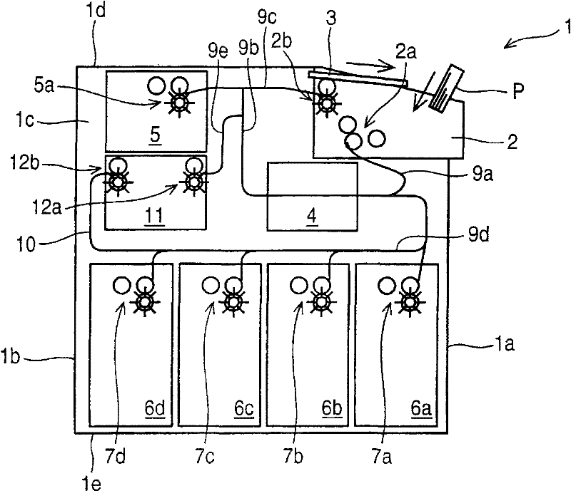
[0025] Below, use Figure 1 to Figure 6 The paper money deposit and withdrawal machine of this embodiment will be described. In addition, with the above Figure 7 The same parts are marked with the same symbols.

[0026] figure 1 Among them, 1 is a banknote deposit and withdrawal machine, which consists of a front panel 1a, a back panel 1b arranged opposite to the front panel 1a, two side panels 1c arranged on both sides of the front panel 1a and the back panel 1b, and the top panel The housing formed by 1d and the bottom plate 1e is equipped with the parts shown below, and is installed in an automatic transaction device such as an automatic teller machine (not shown) as a higher-level device, and has a banknote P inserted by a customer. P performs identification and counting and stores it, and counts the banknotes P paid to the customer and delivers them to the customer.

[0027] 2 is the deposit and withdrawal port of the banknote deposit and withdrawal machine 1, which is arran...


PUM


Abstract

The invention provides a bank note collecting storage facility and a bank note deposit / withdrawal machine equipped with the bank note collecting storage facility, wherein back notes can be smoothly collected by two back note collecting storage facilities arranged opposite to each other. When back notes are laminated along the thickness direction thereof and collected in the bank note collecting storage facility on the workbench between a front panel and a back panel, inlets for the feeding of back notes are respectively arranged above the workbench. A collecting mechanism, a collecting rod and a stopping part are arranged inside each of the inlets. The collecting mechanism is equipped with a feeding roller and a compressing roller pressing the feeding roller for clamping the back notes fed in from the inlet and discharging the back notes on the workbench. The collecting rod is equipped with a guiding part for incling the front end of the back note feeding direction clamped between the feeding roller and the compressing roller toward the guiding direction of the workbench. The stopping part is arranged at the end portion at the downstream of the feeding direction of the guiding part.

Description

Technical field [0001] The present invention relates to a banknote storage in which a plurality of banknotes are stacked in a thickness direction and collected on a workbench, and a banknote deposit and withdrawal machine provided with the banknote storage. Background technique [0002] The conventional banknote deposit and withdrawal machine is equipped with: a deposit and withdrawal port that accepts banknotes inserted by customers; an identification section for identifying the authenticity, damage, and denomination of the conveyed banknotes; and storing banknotes for withdrawal according to their denominations Each denomination box; each denomination temporary holding board arranged on the upper part of each denomination box for temporarily retaining the banknotes put in by the customer; the rejection box for storing the rejected banknotes; the conveying path connecting the above-mentioned parts to convey the banknotes, in the deposit During the transaction, the banknotes iden...

Claims


Application Information

Patent Timeline
Patent Type & Authority Applications(China)
IPC IPC(8): G07D11/00
Inventor 冈田隆司
Owner OKI ELECTRIC IND CO LTD
Why Eureka
Try Eureka