Electric heating film having anti-leakage function

An electric heating film, anti-leakage technology, applied in electric heating devices, ohmic resistance heating, ohmic resistance heating parts and other directions, can solve the problems of low tear resistance, excessive leakage current, affecting the service life of products, etc. The effect of tearing strength, improving thermal conversion power, and improving installation power

Inactive Publication Date: 2011-08-24
DALIAN FUTE TECH DEV
View PDF3 Cites 2 Cited by
  • Summary
  • Abstract
  • Description
  • Claims
  • Application Information

AI Technical Summary

Problems solved by technology

[0003] 1. If the electric heating film installation operation rules are followed, that is, a leakage protector (air switch) is installed in the circuit connecting the conductive heating layer and the power supply, the leakage current generated is enough to make the leakage protector operate, the switch is disconnected, and the electric heating film loses power supply due to But it cannot work normally; and in order to prevent the action of the leakage protector from affecting the work of the electric heating film, cancel the leakage protector (air switch), which does not conform to the operation rules for the installation of the electric heating film, even if the conductive layer leaks due to the reduction of insulation performance, there is no protective measure , there is a security risk;
[0004] 2. Since the leakage current is directly proportional to the frequency and voltage amplitude of the AC power supply, it is necessary to abide by the installation operation regulations and avoid excessive leakage current, which can only reduce the installation power per unit area and affect the heating effect;
[0005] 3. The generated leakage current reduces the thermal conversion efficiency of the electrothermal film and wastes electric energy;
[0006] 4. There is only an insulating layer and no shielding layer outside the conductive heating layer, and the electromagnetic field formed has a slight electric radiation to the human body; in addition, the tear resistance is also low, which affects the service life of the product

Method used


Image

  • Electric heating film having anti-leakage function
  • Electric heating film having anti-leakage function
  • Electric heating film having anti-leakage function

Examples


Embodiment 1

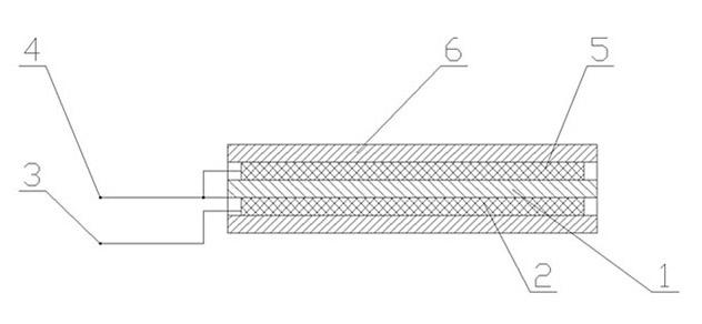
[0018] Such as figure 1 Shown: It has the same upper and lower layers of insulating film 1 as the prior art, and a conductive heating layer 2 is sandwiched between the two layers of insulating film 1. The conductive heating layer 2 is connected to the live wire electrode 3 and the neutral wire electrode 4, and is connected to the current wire electrode 3. The difference between existing technologies is that the upper insulating film 1 is covered with a second conductive layer 5 connected to the neutral electrode 4 , and the second conductive layer 5 is covered with a second insulating layer 6 . The second conductive layer 5 and the insulating film 1 can be fixed as a whole, or can be a split structure. The materials and structures of the second conductive layer 5 and the second insulating layer 6 can be the same as those of the conductive heating layer 2 and the insulating film 1 of the prior art. , it is also possible to add a layer of insulating film between the insulating f...

Embodiment 2

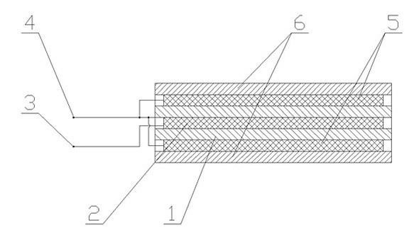
[0022] Such as image 3 Shown: It has the same upper and lower layers of insulating film 1 as the prior art, and a conductive heating layer 2 is sandwiched between the two layers of insulating film 1. The conductive heating layer 2 is connected to the live wire electrode 3 and the neutral wire electrode 4, and is connected to the current wire electrode 3. The difference in existing technology is that the second conductive layer 5 connected to the neutral electrode 4 is covered on the upper surface of the upper insulating film 1 and the lower surface of the upper insulating film 1, and the second conductive layer 5 is coated on the outside. There is a second insulating layer 6 . The second conductive layer 5 and the insulating film 1 can be fixed as a whole, or can be a split structure. The materials and structures of the second conductive layer 5 and the second insulating layer 6 can be the same as those of the conductive heating layer 2 and the insulating film 1 of the prior ...

Embodiment 3

[0024] Such as Figure 4 Shown: the basic structure is the same as that of embodiment 1, the difference from embodiment 1 is that a layer of third conductive layer 7 connected to the ground is covered on the second insulating layer 6, and the outside of the third conductive layer 7 is covered with a third insulating layer8. Similarly, the third conductive layer 7 and the second insulating layer 6 can be fixed as a whole, or can be a split structure. The materials and structures of the third conductive layer 7 and the third insulating layer 8 can be the same as those of the prior art conductive heating Layer 2 and insulating film 1 may also add a layer of insulating film between the second insulating layer 6 and the third conductive layer 7.


PUM


Abstract

The invention discloses an electric heating film having an anti-leakage function, which comprises upper and lower two layers of insulation films, wherein a conductive heating layer is clamped between the two layers of insulation films; the conductive heating layer is connected to a power line electrode and a null line electrode; second conductive layers connected to the null line electrode are covered outside of the insulation films; and second insulation layers are covered outside of the second conductive layers. A loop can be formed between the generated leaked current and the null line electrode, namely the leaked current can be utilized for generating heat, thereby increasing the heat conversion power and saving electric energy as well as avoiding the problem of influence on the normal work of the electric heating film caused by frequently driving a leakage protector to act by the leaked current. The electric heating film can be assembled according to an assembling operation specification for the electric heating film and the potential safety hazard caused by the leakage of the conductive layers can be eliminated, thereby increasing the assembling efficiency in unit area and improving the warming effect.

Description

technical field [0001] The invention relates to an electric heating film, in particular to an electric heating film with the function of preventing electric leakage, which can increase the installation power per unit area, save electric energy, and is safe and reliable. Background technique [0002] At present, electrothermal film has been widely used in geothermal heating for buildings. The existing electric heating film is equipped with upper and lower insulating films (made of PVC, PET, PC, PI and other materials), and a conductive heating layer (conductive ink or metal film lines, carbon fiber, etc.) is sandwiched between the two insulating films. , The conductive heating layer is connected to the live wire electrode and the neutral wire electrode. When in use, the live wire electrode is connected to the mains 220V voltage live wire, and the neutral wire electrode is connected to the mains 220V voltage neutral wire. Due to the large heating area of ​​the electrothermal ...

Claims


Application Information

Patent Timeline
Patent Type & Authority Applications(China)
IPC IPC(8): H05B3/34H05B3/02
Inventor 栾松张天末栾文彦栾雨泽
Owner DALIAN FUTE TECH DEV
Why Eureka
Try Eureka