Air jet spinning unit having spindle-shaped component

A technology of air-jet spinning and parts, which is applied in the field of mandrel-shaped parts, which can solve the problems of processing costs and other problems, and achieve the effect of simplifying processing and assembly costs and eliminating fiber aggregation

Active Publication Date: 2011-08-24
MASCHINENFABRIK RIETER AG
View PDF8 Cites 8 Cited by
  • Summary
  • Abstract
  • Description
  • Claims
  • Application Information

AI Technical Summary

Problems solved by technology

The complex structure of the air-jet spinning device makes the processing labor-intensive

Method used


Image

  • Air jet spinning unit having spindle-shaped component
  • Air jet spinning unit having spindle-shaped component
  • Air jet spinning unit having spindle-shaped component

Examples


Embodiment Construction

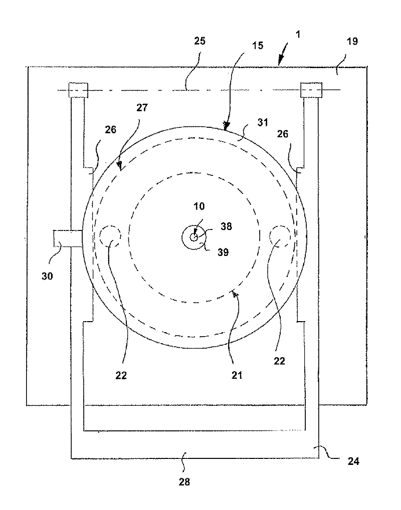
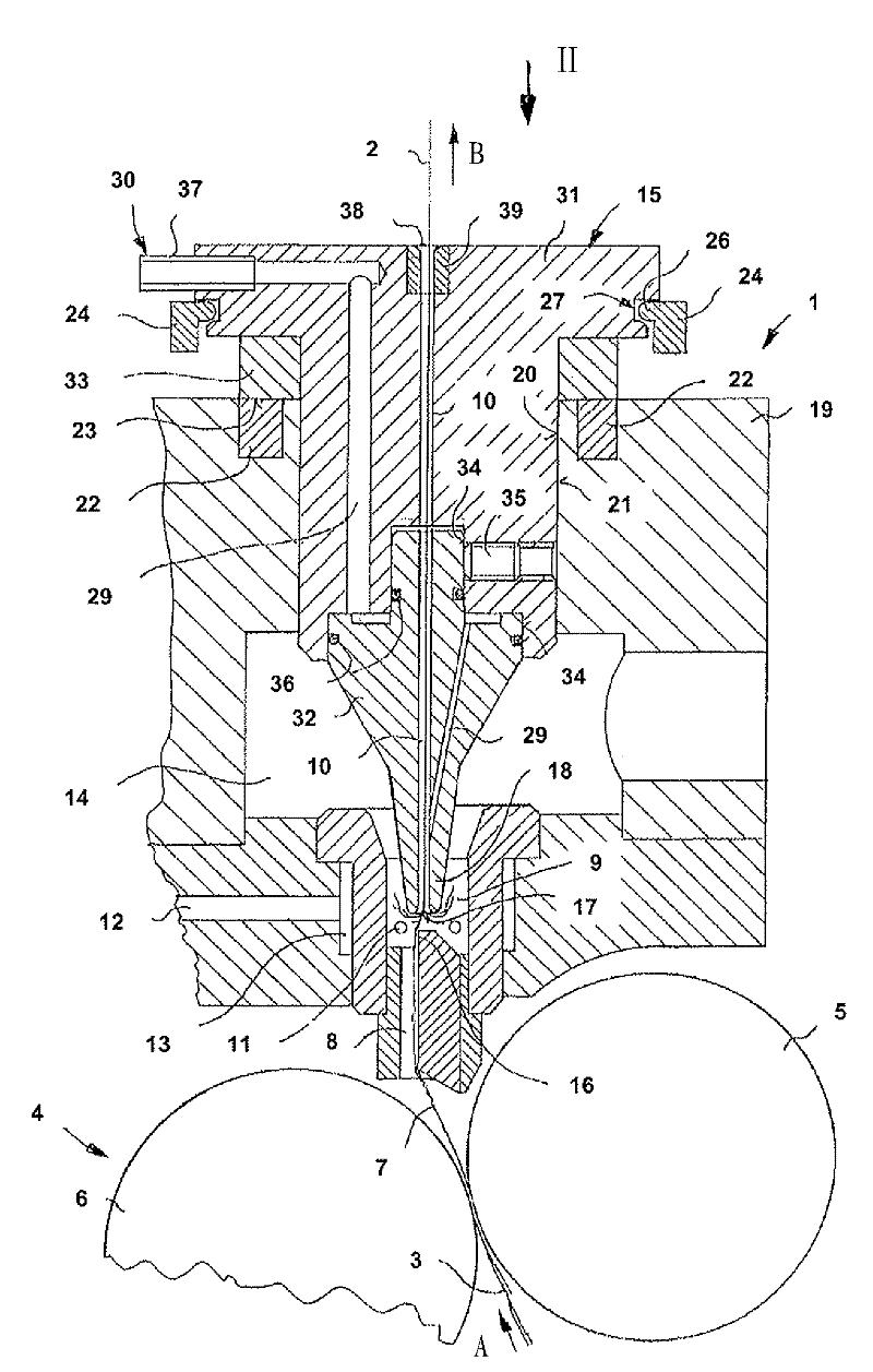
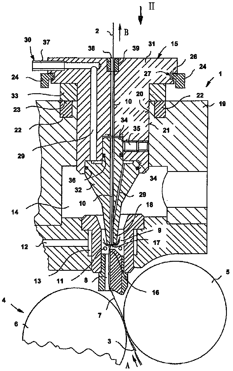
[0020] exist figure 1 The air-jet spinning device shown in is used for processing a spun yarn 2 from a staple fiber sliver 3 . The drafting device 4 is placed in front of the air-jet spinning device 1 .

[0021] The staple fiber strand 3 to be spun is transported in the drafting device 4 in the drafting direction A and is discharged as spun yarn 2 in the yarn discharge direction B and is passed on to a winding device (not shown). The drafting device 4 , which is only partially shown, is preferably a three-roller drafting device and therefore contains a total of three roller pairs, which each have a driven bottom roller and an upper roller formed by pressure rollers. Only the feed roller pairs 5 , 6 which limit the drafting range of the drafting device 4 are shown. In this drafting device 4, the staple fiber strand 3 is drafted to the desired fineness in a known manner. Then the thin fibrous strands 7 appear on the clamping line of the feed roller pair 5,6 in the drafting de...


PUM

PropertyMeasurementUnit
lengthaaaaaaaaaa

Abstract

An air jet spinning unit comprises a spindle-shaped component. The spindle-shaped component comprises a thread pulloff channel (10) and can be moved along the thread pulloff channel. The air jet spinning unit comprises at least one magnet (22) for holding the spindle-shaped component in the operating position thereof.

Description

technical field [0001] The invention relates to an air-jet spinning device having a mandrel-shaped part which has a yarn discharge channel and which is movable along the yarn discharge channel. [0002] The invention also relates to a mandrel-shaped part for an air-jet spinning device with a yarn discharge channel, with a cylindrical sliding surface for receiving inside the air-jet spinning device and with a conically converging mandrel tip, which contains the row Access hole for yarn channel. Background technique [0003] An air-jet spinning device of the above-mentioned type is known from DE 10 2004 044 345 A1. A spring and a pneumatic cylinder are integrated in known air-jet spinning devices for moving the mandrel-shaped part. The complex construction of the air-jet spinning device makes processing complex. [0004] An air-jet spinning device is known from DE 195 01 545 A1, in which the movement and fixing devices for the mandrel-shaped components are not integrated in...

Claims


Application Information

Patent Timeline
Patent Type & Authority Applications(China)
IPC IPC(8): D01H1/115D01H4/02
CPCD01H4/02D01H1/115
Inventor P·施韦尔
Owner MASCHINENFABRIK RIETER AG
Why Eureka
Try Eureka