Quick-change drill chuck

A drill chuck and chuck technology, applied in the field of tools, can solve problems such as inconvenient and awkward operation

Active Publication Date: 2011-08-31
NANJING JIUCHI ELECTROMECHANICAL IND
View PDF11 Cites 8 Cited by
  • Summary
  • Abstract
  • Description
  • Claims
  • Application Information

AI Technical Summary

Problems solved by technology

However, when inserting, since the external force applied to the unlocking ring is opposite to the direction of insertion, the operation is awkward and not convenient enough

Method used


Image

  • Quick-change drill chuck
  • Quick-change drill chuck
  • Quick-change drill chuck

Examples


Embodiment 1

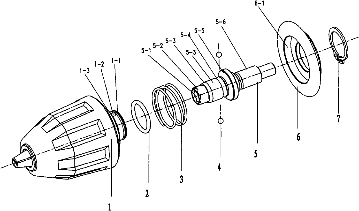
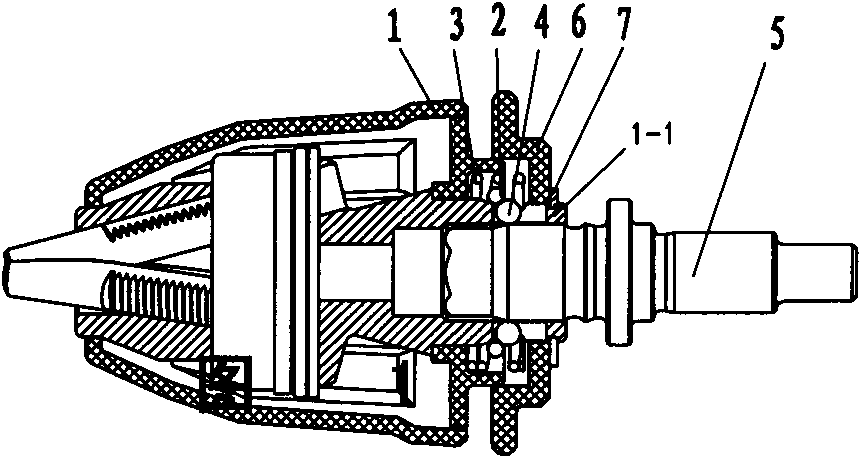
[0022] The quick-change drill chuck of the present embodiment is as figure 1 As shown, it is mainly composed of a collet body 1 that can form a circumferential constraint with the output shaft, a compression spring 3 , an unlocking ring 6 and an electric drill output shaft 5 . The middle part of the rear end surface of the chuck body 1 extends out of the sleeve 1-1 and the outer ring 1-3 whose inner hole is in clearance fit with the output shaft 5. Parts—the axially extending long perforations 1-2 of the steel ball 4. The outer end of the sleeve pipe 1-1 is equipped with a circlip 7 for the shaft.

[0023] The end of the output shaft 5 has an inner hexagonal screwdriver socket 5-1, the front part has an outer hexagonal non-circular section 5-2 that can form a circumferential constraint with the corresponding structure of the casing, and the middle cylindrical section has a 5-3 The annular groove 5-4 that steel ball matches. The outer hexagonal non-circular section 5-2 conne...

Embodiment 2

[0029] The difference between this embodiment and Embodiment 1 is that the radial elastic member adopts Figure 7The effect of the split elastic ring shown is similar to that of the ring spring in Embodiment 1, and can be deduced by analogy. Other structures are the same as those in Embodiment 1, and will not be repeated here.

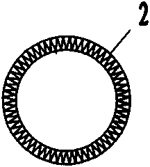
[0030] In addition to the annular spring and the split elastic ring, the above radial elastic members can also adopt other variable structures, such as a ring structure with internal teeth, and the ring has elastic inner teeth inclined towards the axial direction. When the blade is elastically deformed in the axial direction by the axial force, the inner diameter of the envelope formed by the tooth top of the inner gear blade will also expand elastically.


PUM


Abstract

The invention relates to a quick-change drill chuck which belongs to the technical field of tools. The drill chuck mainly comprises a chuck body, a compression spring, an unlocking ring and an electric-drill output shaft; when the unlocking ring is shoved out by the compression spring, so that the unlocking ring is arranged away from the rear end face of the chuck body, and the tapered transitionsection of the unlocking ring is pressed against a meshing component, so that a radial elastic component is in a diameter expanding state, the radial elastic component is in the state that through carrying out diameter shrinkage and extrusion on the meshing component, the radial elastic component is close to the end of a slot hole away from the chuck body, and the radial elastic component is dropped into a groove and performed perforation by the unlocking ring so as to carry out radial constraint on the unlocking ring; when the unlocking ring overcoming the compression spring is arranged at the position close to the rear end face of the chuck body, the radial elastic component is subjected to axial displacement and diameter expanding with the unlocking ring along the tapered section of a sleeve so as to respectively break away the extrusion and radial constraint on the meshing component. After the quick change drill chuck provided by the invention is adopted, because the unlocking ring is not required to be controlled in the whole process of inserting the unlocking ring into the chuck body, and the forced direction acted on the unlocking ring and the pullout direction of the unlocking ring are consistent when the unlocking ring is pulled out from the chuck body, the operation of inserting the unlocking ring into the chuck body or pulling the unlocking ring out from the chuck body is handy and very convenient.

Description

technical field [0001] The invention relates to a drill chuck, in particular to a quick-change drill chuck, which belongs to the technical field of tools. Background technique [0002] A hand-held electric drill is a very commonly used power tool. In order to meet the needs of drilling and screwing, people have developed a drill chuck that can be quickly replaced. [0003] Patent documents such as EP1236538B1, EP1946894A1, US2010108338A1, US6550786B2, US7331738B2, and US7793572B2 respectively disclose quick-change drill chucks with various typical structures. However, the structures of these quick-change drill chucks are relatively complicated. [0004] The German patent with the patent number DE20016090U1 discloses a quick-change drill chuck with simple structure and low cost. The electric drill output shaft is composed of the front end of the output shaft with a non-circular section matching the corresponding structure of the casing, and the middle part with a cylindrica...

Claims


Application Information

Patent Timeline
Patent Type & Authority Applications(China)
IPC IPC(8): B23B31/10
Inventor 吹拔正敏
Owner NANJING JIUCHI ELECTROMECHANICAL IND
Why Eureka
Try Eureka