
Multi-mode passive tag

A technology of passive tags and microstrip antennas, which is applied to record carriers used by machines, instruments, computer components, etc., can solve problems such as increasing R&D, production and application costs, limiting tag flexibility, and suppressing system versatility. Achieve the effects of convenient control, simple production and processing technology, and low cost

Inactive Publication Date: 2011-08-31
陈立强
View PDF3 Cites 8 Cited by
  • Summary
  • Abstract
  • Description
  • Claims
  • Application Information

AI Technical Summary

Problems solved by technology

Since the current communication processing chip only works for a specific frequency and a specific standard, that is to say, a communication processing chip can only transmit and receive reader signals of one frequency band and standard when it is working. If the reading system is replaced, the label must be replaced. Therefore, every A passive radio frequency tag can only work at a single frequency, which greatly limits the flexibility of tag use, and also greatly inhibits the versatility of the system, thereby increasing the cost of research and development, production and application

Method used


Image

  • Multi-mode passive tag
  • Multi-mode passive tag
  • Multi-mode passive tag

Examples


Embodiment 1

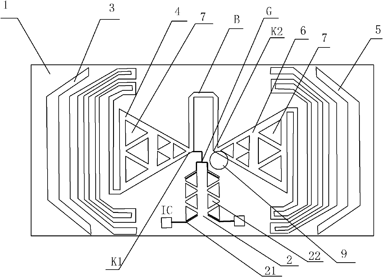
[0026] Embodiment 1: a dual-mode passive label, including a substrate 1, the front of the substrate 1 is provided with a printed dipole antenna, a printed microstrip combiner 2 and two communication processing chip ICs, and the printed dipole antenna includes The first part antenna and the second part antenna with the same structure and symmetrical distribution, the first part antenna has a first feed end K1, the second part antenna has a second feed end K2, the first feed end K1 and the second feed end A balanced and unbalanced converter B is arranged between K2, the printed microstrip combiner 2 includes a common terminal G and two discrete terminals 21, and the common terminal G of the printed microstrip combiner 2 is connected to the first feeding terminal K1 Each discrete end 21 of the printed microstrip combiner 2 is connected to a communication processing chip IC. The two communication processing chip ICs are the high-frequency tag chip model SRF55V10P and the low-frequ...

Embodiment 2

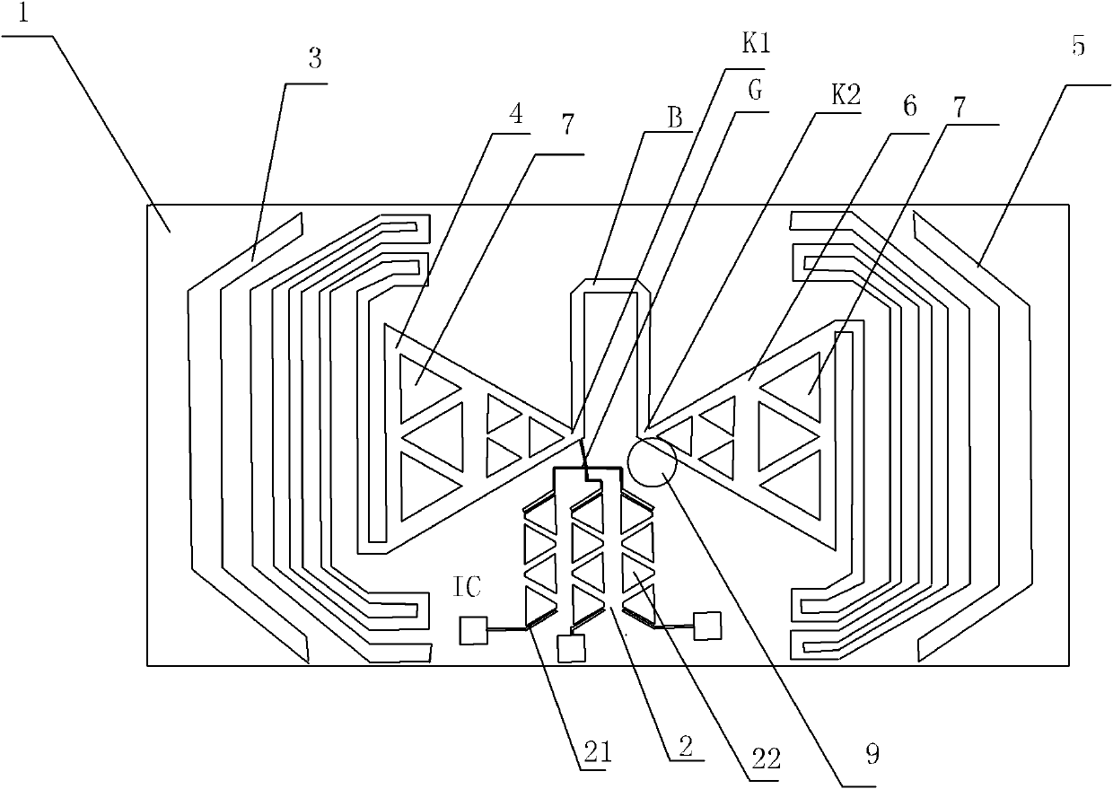
[0029] Embodiment 2: A three-mode passive tag, other parts are the same as the dual-mode passive tag in Embodiment 1, the difference is that there are three communication processing chips IC, and the printed microstrip combiner 2 includes a three-way filter , the printed microstrip combiner 2 has three discrete terminals 21, and each discrete terminal 21 is connected to a communication processing chip IC. By analogy, the structure of other multi-mode passive tags can be known. There are various types and specifications of the communication processing chips here. The three communication processing chips are the high-frequency tag chip model SRF55V10P, the UHF tag chip model UCODE SL3 IC S10 and the low-frequency tag chip model HITAG S. .


PUM


Abstract

The invention discloses a multi-mode passive tag, which comprises a substrate, wherein a printed dipole antenna, a printed microstrip combiner and a plurality of communication processing chips are arranged on the front side of the substrate; the printed dipole antenna comprises a first antenna and a second antenna, which have the same structure and distributed symmetrically; the first antenna hasa first feed terminal and the second antenna has a second feed terminal; a balance and unbalance converter is arranged between the first feed terminal and the second feed terminal; the printed microstrip combiner comprises a public terminal and a plurality of separate terminals; the public terminal of the printed microstrip combiner is connected with the first feed terminal; and each separate terminal of the printed microstrip combiner is connected with a communication processing chip. The multi-mode passive tag has the advantages that: 1, the production and processing process is simple, and the cost is low; 2, the antenna can transmit and receive more than two radio frequency signals; and 3, the application of the microstrip combiner allows different radio frequency signals to perform operation on one radio frequency tag at the same time, namely multi-mode operation.

Description

technical field [0001] The invention relates to a wireless identification module, in particular to a multimode passive tag. Background technique [0002] Radio Frequency Identification (RFID) is a non-contact automatic identification radio frequency technology, which automatically identifies target objects and obtains relevant data through radio frequency identification signals. Since the RFID identification work does not require human intervention, it can work in various harsh environments. Based on this feature, RFID, an automatic wireless identification and data acquisition technology, has been widely used in many fields, and is closely integrated with modern logistics, transportation, monitoring and Internet technologies. [0003] A brief description of the RFID system and its working principle: The RFID system mainly includes readers, reader antennas and tags. During the working process of the RFID system, the reader will control the radio frequency module in the RFID...

Claims


Application Information

Patent Timeline
IPC IPC(8): G06K19/08
Inventor 陈立强
Owner 陈立强
Learn More