Clamping device for positioning tube socket
A technology of positioning clamping and tube sockets, which is applied to laser parts, electrical components, lasers, etc., can solve the problems of low production efficiency, few tube sockets, complex structure, etc., and achieve simple structure, fast replacement of tube sockets, convenience and reliability The effect of clamping
- Summary
- Abstract
- Description
- Claims
- Application Information
AI Technical Summary
Problems solved by technology
Method used
Image

Examples
Embodiment Construction
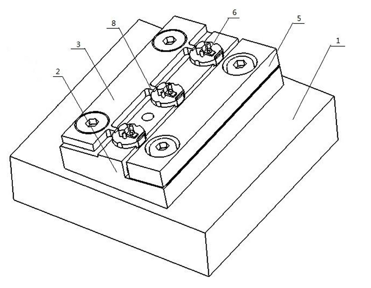
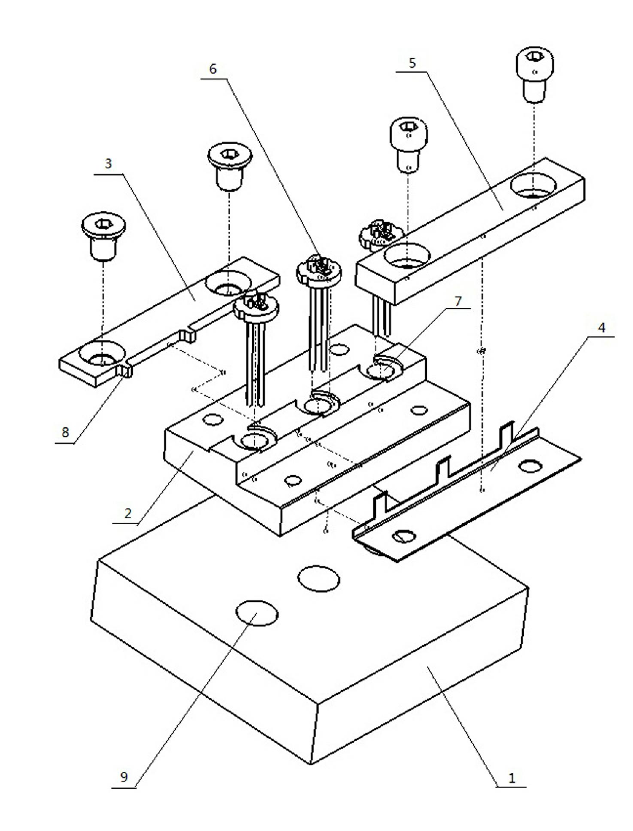
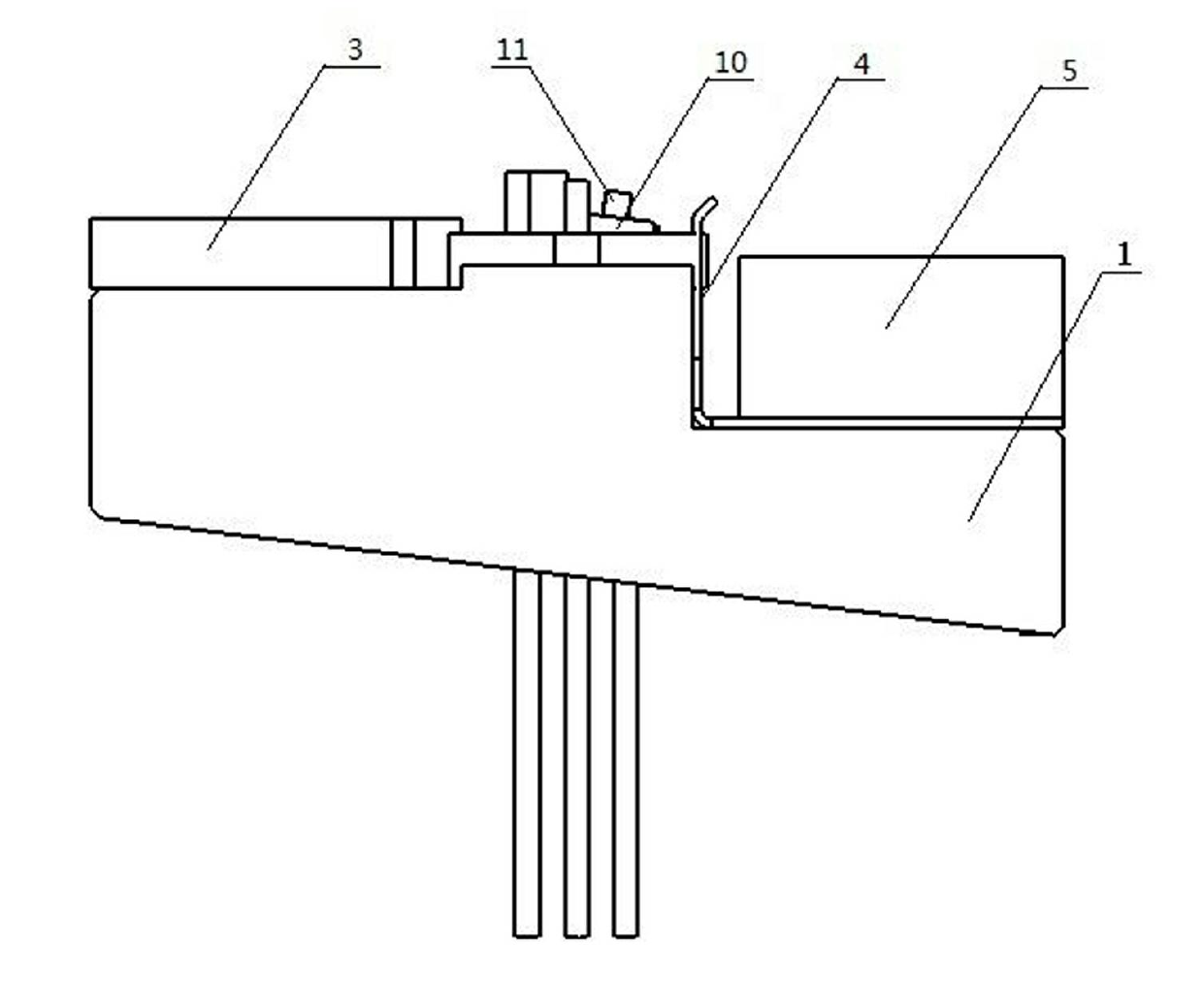
[0013] as attached figure 1 Shown in -4 is a specific embodiment of the present invention, which includes a base 1, a material receiving seat 2 arranged on the base 1, a positioning bar 3 arranged on one side of the material receiving seat 2, and a spring for fixing the spring leaf 4 Compression bar 5, the material receiving seat 2 is provided with a round hole 7 for placing the tube seat 6, and one side of the positioning bar 3 is provided with a boss 8 for being stuck in the U-shaped groove 12 on the tube seat 6 , the spring sheet 4 is arranged between the material receiving seat 2 and the pressing strip 5, the base 1 is provided with a round hole 9 for piercing the tube seat 6, the lower plane of the material receiving seat 2 is in contact with the tube The adhesive sheet platform 10 on the seat 6 is arranged in parallel.
[0014] During use, the outer circle of the stem 6 of the TO56 infrared semiconductor laser is placed in the round hole 7 of the material holder 2 of th...
PUM
 Abstract
Description
Claims
Application Information
 - Generate Ideas
- Intellectual Property
- Life Sciences
- Materials
- Tech Scout
- Unparalleled Data Quality
- Higher Quality Content
- 60% Fewer Hallucinations
Browse by: Latest US Patents, China's latest patents, Technical Efficacy Thesaurus, Application Domain, Technology Topic, Popular Technical Reports.
© 2025 PatSnap. All rights reserved.Legal|Privacy policy|Modern Slavery Act Transparency Statement|Sitemap|About US| Contact US: help@patsnap.com