Display device
A technology of indicators and pointers, which is applied to the direction of indicating elements, indications of measured values, instruments, etc., and can solve problems such as setting another indicating device
- Summary
- Abstract
- Description
- Claims
- Application Information
AI Technical Summary
Problems solved by technology
Method used
Image

Examples
Embodiment 1
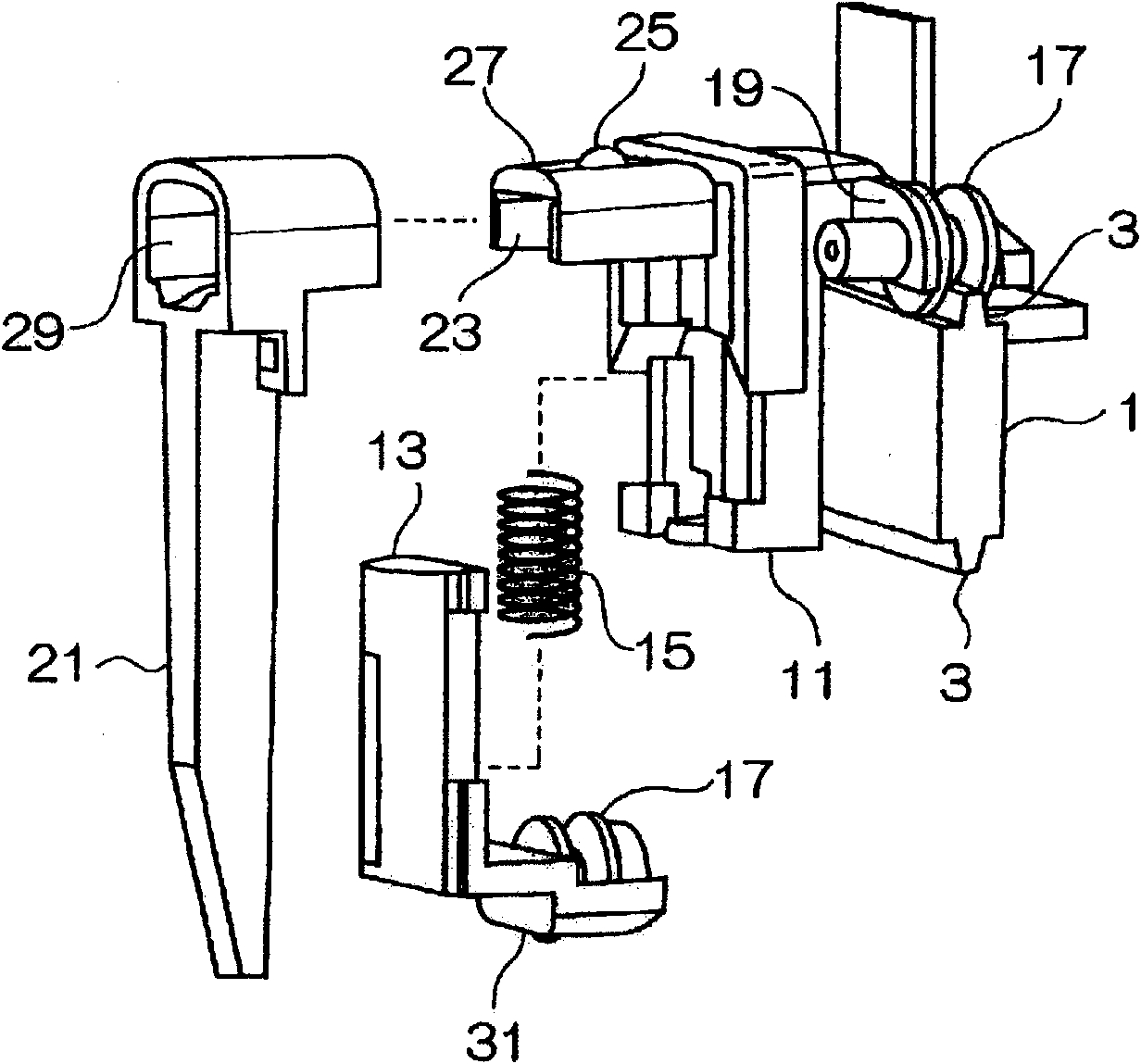
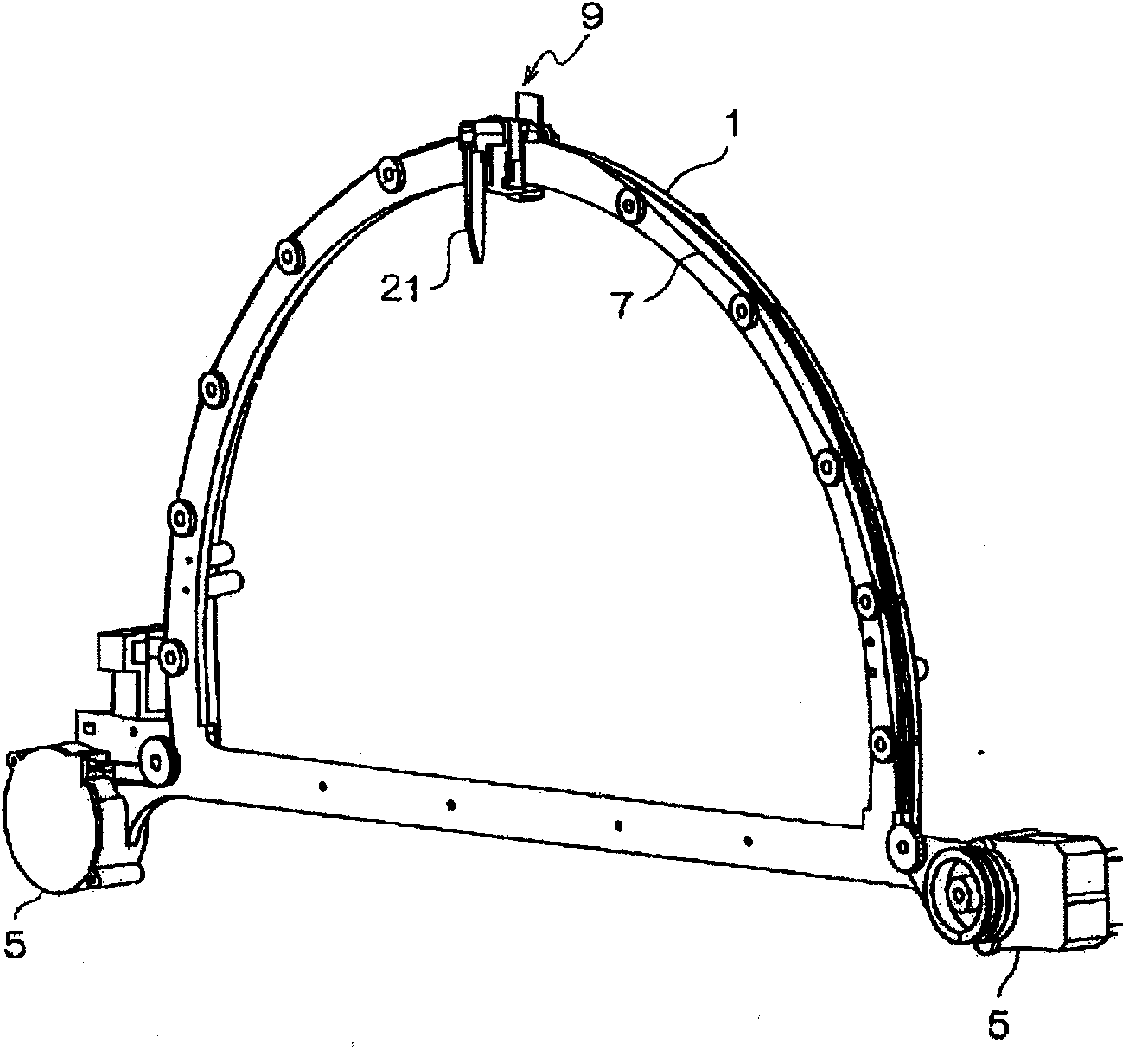
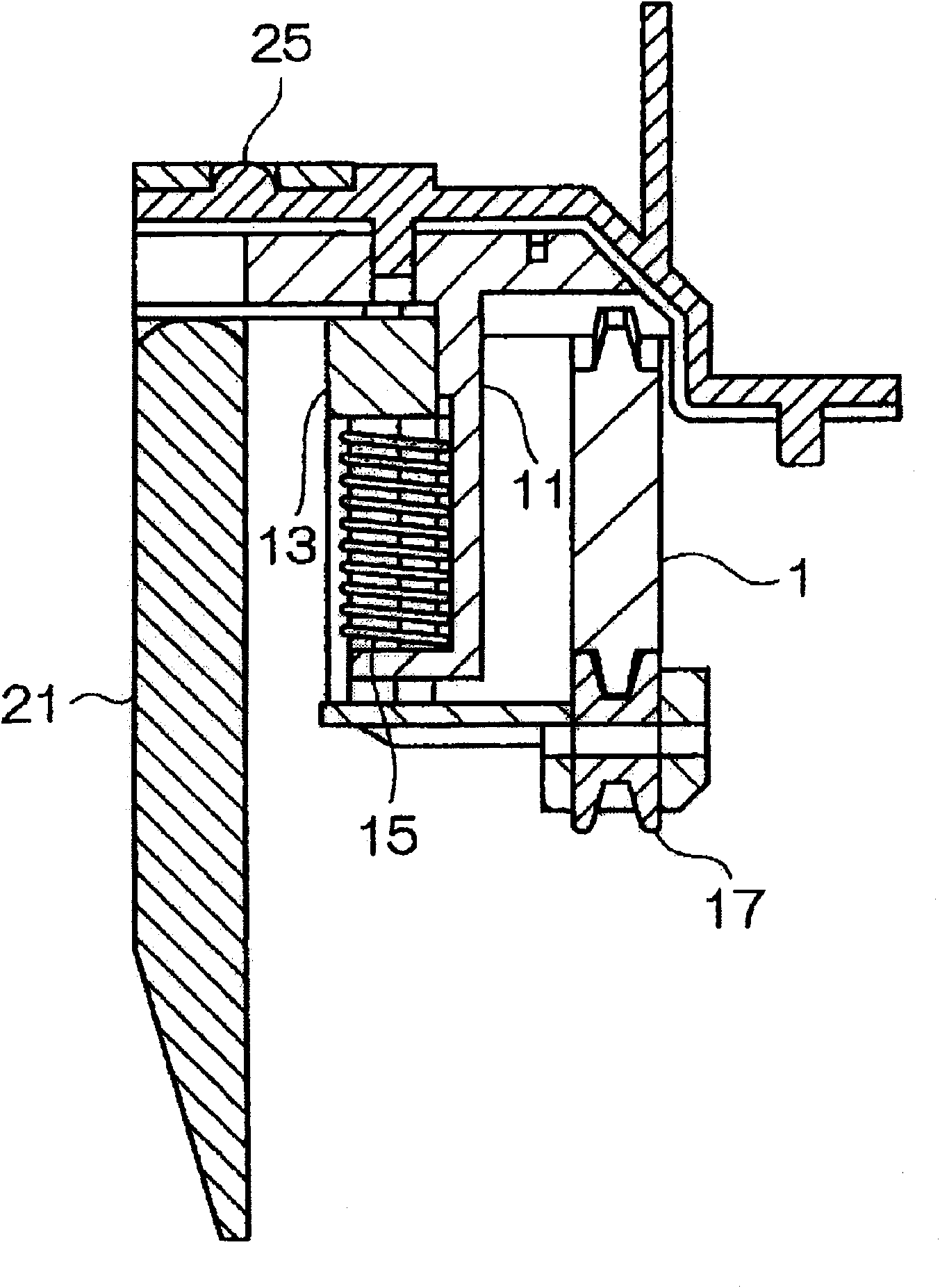
[0069] figure 1 It is a structural diagram of the moving part provided on the indicator of Embodiment 1 of the present invention, figure 2 is the overall view of the rail, while image 3 is a cross-sectional view of the moving member clamping the guide rail, taken along the direction in which the guide rail extends. The indicator of the present embodiment is, for example, a centerless gauge indicating the speed of the motor vehicle and having scales arranged in an arc on the outer peripheral side of the semicircular dial surface. A space where a liquid crystal indicator can be placed is formed inside the scale and enables the guide rail 1 to be placed on the back side of the dial. As shown in the figure, the guide rail 1 is formed by extending a plate-shaped member in an arc shape so that the direction in which the guide rail 1 extends coincides with the direction in which the scales are arranged on the scale. Bosses 3 are formed on the outer and inner peripheral surfaces ...
Embodiment 2
[0084] Preferably the moving parts and pointers used in embodiment 1 are in Figure 11 Shown in, as Example 2. As shown in the drawing, the moving piece and pointer of Embodiment 2 is different from that of Embodiment 1 in that the restricting piece 60 formed to protrude from the pointer 21 is inserted into the groove formed in the upper part of the supporting piece 13 62 in. Other configurations are still the same as in Embodiment 1, and therefore, the same reference numerals are assigned to the same parts as in Embodiment 1 to omit description thereof.
[0085] Such as Figure 12 As shown, the restricting member 60 is inserted at right angles to the direction in which the spring member 15 expands. The groove 62 is formed to have a gap 64 into which the restrictor 60 is inserted. When moving part 9 and pointer 21 are installed on guide rail 1, as Figure 13 As shown, after the guide rail 1 is clamped by the moving part 9 , the pointer 21 is installed on the moving part 9...
Embodiment 3
[0091] will use Figure 14 and 15 The indicator of Embodiment 3 will be described. Figure 14 is an exploded view of the indicator of embodiment 3, and Figure 15 The main part of Embodiment 3 is shown. Such as Figure 14 As shown, Embodiment 3 is configured such that: a semicircular space 103 capable of placing a liquid crystal indicator etc. is formed inside the semicircular dial 100, which is not shown in Embodiment 1; A scale 105 is formed on the dial 100 along the outer circumference of the space 103 ; and a pointer 21 is located in the space 103 to indicate the scale on the scale 105 . Embodiment 1 differs from Embodiment 3 in that the pointer 21 is located on the outer peripheral side of the dial, and the pointer 21 points to the inner peripheral side of the guide rail 1 . However, the pointing of the pointer 21 is not the main content of the present invention, so it can be selected according to needs. Furthermore, in Embodiment 3, the pointer 21 is provided on th...
PUM
 Abstract
Description
Claims
Application Information
 - R&D
- Intellectual Property
- Life Sciences
- Materials
- Tech Scout
- Unparalleled Data Quality
- Higher Quality Content
- 60% Fewer Hallucinations
Browse by: Latest US Patents, China's latest patents, Technical Efficacy Thesaurus, Application Domain, Technology Topic, Popular Technical Reports.
© 2025 PatSnap. All rights reserved.Legal|Privacy policy|Modern Slavery Act Transparency Statement|Sitemap|About US| Contact US: help@patsnap.com