Apparatus and method for sensing a current leakage of a battery, and battery driving apparatus and battery pack including the apparatus

一种泄漏电流、泄漏电阻的技术,应用在测量电流/电压、电池组零部件、测量电阻/电抗/阻抗等方向,能够解决泄漏电流、电池不良、电池电击等问题,达到防止确定精度的变差、精确泄漏电流、减少噪声的效果

Active Publication Date: 2011-08-31
LG ENERGY SOLUTION LTD
View PDF8 Cites 27 Cited by
  • Summary
  • Abstract
  • Description
  • Claims
  • Application Information

AI Technical Summary

Problems solved by technology

Poor insulation of the battery causes leakage current, which leads to various problems
For reference, leakage current of the battery causing accidental discharge of the battery, or failure of electronic equipment included in the device
Also, the leakage current of batteries used in equipment using high-voltage batteries such as electric vehicles can cause fatal electric shocks to people

Method used


Image

  • Apparatus and method for sensing a current leakage of a battery, and battery driving apparatus and battery pack including the apparatus
  • Apparatus and method for sensing a current leakage of a battery, and battery driving apparatus and battery pack including the apparatus
  • Apparatus and method for sensing a current leakage of a battery, and battery driving apparatus and battery pack including the apparatus

Examples


Embodiment Construction

[0031] Preferred embodiments of the present invention will be described in detail with reference to the accompanying drawings. Before the description, it should be understood that the terms used in the specification and appended claims should not be interpreted as limited to the general and dictionary meanings, but should be based on allowing the inventors to properly define the terms to obtain the best interpretation The principles of the present invention are interpreted based on the meanings and ideas corresponding to the technical aspects of the present invention. Therefore, the descriptions set forth herein are preferred examples for illustrative purposes only, and are not intended to limit the scope of the present invention, and it should be understood that other equivalents may be established thereto without departing from the spirit and scope of the present invention. objects and modifications.

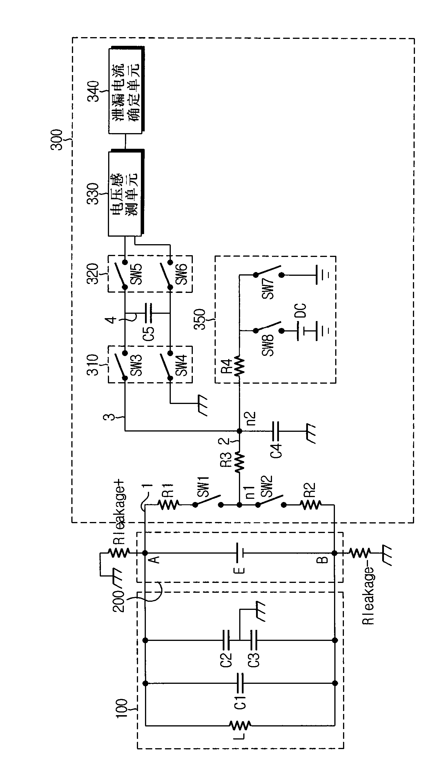
[0032] figure 1 is a circuit diagram showing an apparatus for sensing ...


PUM


Abstract

The present invention relates to an apparatus and to a method for sensing a current leakage of a battery, and to a battery driving apparatus and to a battery pack including the apparatus. The apparatus for sensing a current leakage of a battery according to the present invention includes: a floating capacitor for storing voltages detected from an anode terminal or a cathode terminal of a battery; a DC voltage applying unit for applying DC voltage to the cathode terminal when the voltage detected from the cathode terminal of the battery is measured; a terminal selection switching unit for selecting a voltage detection path of the anode terminal or the cathode terminal; a charging switch unit for charging the floating capacitor with the detected voltage of the anode terminal or the cathode terminal detected from the selected voltage detection path, and separating the floating capacitor from the voltage detection path; a voltage sensing unit for sensing the detected voltage of the anode terminal or the cathode terminal of the battery charged in the separated floating capacitor; and a current leakage determination unit for calculating a leakage resistance by using the detected voltage of the anode terminal and the cathode terminal of the battery sensed by the voltage sensing unit, and determining whether or not a current leakage has occurred through the comparison of the calculated leakage resistance and a reference insulation resistance.

Description

technical field [0001] The present invention relates to an apparatus and method for sensing a leakage current of a battery, and more particularly to an apparatus and method for sensing a leakage current of a battery employed in a battery power supply system requiring a high voltage, such as an electric vehicle and a hybrid vehicle. method. Background technique [0002] Recently, with the exhaustion of fossil fuels and environmental pollution, electric vehicles or hybrid vehicles (hereinafter, collectively referred to as electric vehicles) that can be driven by batteries without using fossil fuels have become more attractive. [0003] Most batteries used for electric vehicles are secondary batteries. Secondary batteries are classified into lithium series batteries and nickel hydrogen series batteries. Lithium series batteries are mainly applied to small-sized products such as digital cameras, P-DVD, MP3P, cellular phones, PDAs, portable game devices, electric tools and elec...

Claims


Application Information

Patent Timeline
Patent Type & Authority Applications(China)
IPC IPC(8): G01R31/02H01M10/48G01R19/00H01M50/569
CPCY02E60/12H01M10/482G01R27/18G01R31/025H01M10/42G01R31/362B60L3/0069H01M10/052H01M10/48Y02T10/7011G01R31/3835G01R31/52Y02E60/10H01M50/569G01R27/08G01R31/36
Inventor 康柱铉金智浩李相勋权洞槿
Owner LG ENERGY SOLUTION LTD
Why Eureka
Try Eureka