Pneumatic connection rod type rotary cutting mould

A connecting rod type, mold technology, applied in the field of mold manufacturing, can solve the problems of inability to continuously produce, inaccurate product positioning, low parts manufacturing accuracy and production efficiency, and achieves improving market competitiveness, saving a lot of costs, and improving production efficiency. Effect

Active Publication Date: 2011-09-07
LEMTECH PRECISION MATERIAL (CHINA) CO LTD
View PDF5 Cites 13 Cited by
  • Summary
  • Abstract
  • Description
  • Claims
  • Application Information

AI Technical Summary

Problems solved by technology

[0002] At present, some locks, automobile starter motors, electric motors and other straight rotary deep-drawn parts, as well as bottomless rotary deep-drawn parts, cannot be mass-produced in ordinary progressive dies with ordinary stamping equipment. There are two reasons for the production of this type of parts: First, because the rotary cutting die set in the clamping plate is very long, when the mold is closed, the rotary cutting die will be ahead of the guiding mechanism of the mold (such as the guide pin) Contact with the material belt or product, resulting in inaccurate product positioning, unable to complete complete continuous production; second, the rotary cutting die set on the upper mold must be completely separated from the material belt before feeding, because the rotary cutting die It is very long. It is the last to leave the material belt when the mold is opened, and it is the first to contact the material belt when the mold is closed. Therefore, the feeding time of the feeder is too short to make continuous production. Therefore, due to th

Method used


Image

  • Pneumatic connection rod type rotary cutting mould
  • Pneumatic connection rod type rotary cutting mould
  • Pneumatic connection rod type rotary cutting mould

Examples


specific Embodiment approach

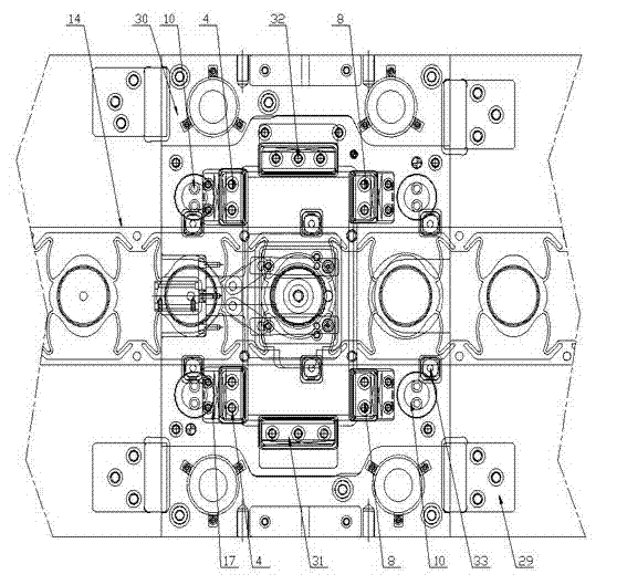
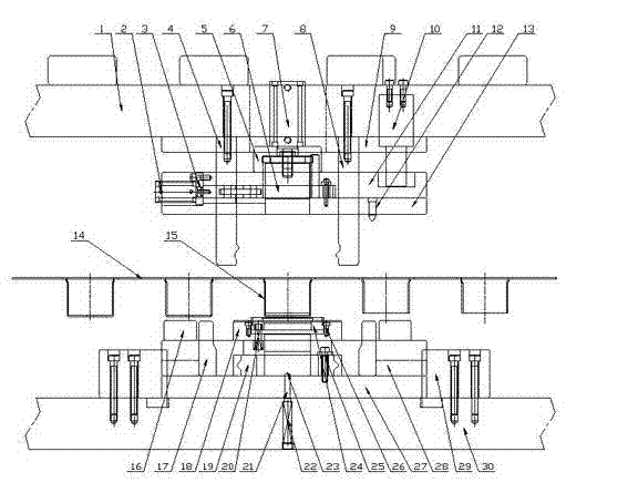
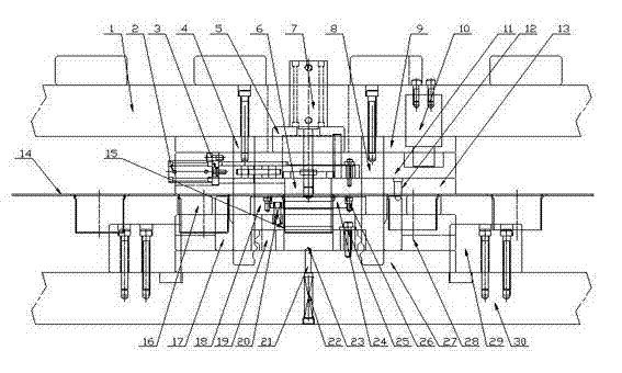
[0042] figure 1 It is a partial front view of an embodiment of the present invention; figure 2 It is a side view of an embodiment of the present invention in a mold-opening state; image 3 It is a side view of an embodiment of the present invention in a closed mold state; Figure 4 It is a left side view of an embodiment of the present invention.

[0043] Such as Figure 1-Figure 4 Shown: Pneumatic connecting rod type rotary cutting die, including upper die and lower die, of which:

[0044] The upper mold includes upper mold base 1, punch fixing plate 9, unloading plate 11 and pressure plate 13 from top to bottom. Nitrogen spring 10 for pressing and unloading is arranged in upper mold base 1, and pressure plate 13 A rotary cutting die 6 and a guide pin 12 are arranged inside, wherein the rotary cutting die 6 is located in the middle of the press plate 13, and the guide pin 12 is located on the inner side of the press plate 13 to guide the strip. effect;

[0045]The lowe...


PUM


Abstract

The invention discloses a pneumatic connection rod type rotary cutting mould which comprises an upper mould and a lower mould, wherein the upper mould comprises an upper mould seat, a convex mould fixing plate, a discharge plate and a pressure plate; a nitrogen spring is arranged in the upper mould seat; a rotary cutting concave mould and a guide pin are arranged in the pressure plate; the lower mould comprises a lower mould plate, a lower base plate and a lower mould seat; a rotary cutting convex mould is arranged in the limit grooves arranged on the upper surface of the lower base plate and the lower end surface of the lower mould plate, and corresponds to the rotary cutting concave mould; the lower part of the rotary cutting convex mould is also provided with a rotary cutting convex mould resetting mechanism; in the convex mould fixing plate, a front driving block, a rear driving block, a left driving block and a right driving block of the rotary cutting convex mould are also arranged in the front, rear, left and right directions of the mould; the four driving blocks cooperate with the outer side of the rotary cutting convex mould; and a pneumatic connection rod mechanism is arranged in a limit groove formed by the upper surface of the pressure plate and the lower end surface of the discharge plate. The pneumatic connection rod type rotary cutting mould disclosed by the invention not only can guarantee the product precision and improve the production efficiency, but also finish all processes in a set of progressive mould, thereby greatly saving the cost and improving the market competitiveness.

Description

technical field [0001] The invention relates to a stamping progressive die, more specifically to a pneumatic connecting rod type rotary cutting progressive die, which belongs to the technical field of die manufacturing. Background technique [0002] At present, some locks, automobile starter motors, electric motors and other straight rotary deep-drawn parts, as well as bottomless rotary deep-drawn parts, cannot be mass-produced in ordinary progressive dies with ordinary stamping equipment. There are two reasons for the production of this type of parts: First, because the rotary cutting die set in the clamping plate is very long, when the mold is closed, the rotary cutting die will be ahead of the guiding mechanism of the mold (such as the guide pin) Contact with the material belt or product, resulting in inaccurate product positioning, unable to complete complete continuous production; second, the rotary cutting die set on the upper mold must be completely separated from the...

Claims


Application Information

Patent Timeline
IPC IPC(8): B21D28/14B21D37/10
Inventor 张亮李配宇陶志华
Owner LEMTECH PRECISION MATERIAL (CHINA) CO LTD
Why Eureka
Try Eureka