Stamping die and light guide plate thereof

A technology for pressing templates and molds, applied in the directions of light guide, printing, optics, etc., can solve the problems of the deterioration of the optical rotation performance of the light guide plate, the inconvenient structure of printing and pressing molds, and the inability to completely press the optical microstructure pattern, so as to improve the product life. Effect

Inactive Publication Date: 2011-09-07
苏州向隆塑胶有限公司
View PDF6 Cites 4 Cited by
  • Summary
  • Abstract
  • Description
  • Claims
  • Application Information

AI Technical Summary

Problems solved by technology

[0005] In this way, if the protrusions 420 around the micro-holes 440 are bent or collapsed and fall into the micro-holes 440 to fill the micro-holes 440, it will cause the printing mold to print the optical microstructure pattern on the light guide plate. When the press is working, the complete optical microstructure pattern cannot be printed completely, which will lead to the deterioration of the optical rotation performance of the light guide plate
[0006] This shows that the structure of the above-mentioned embossing mold still has inconvenience and defects, and needs to be further improved
In order to solve the above problems, related fields have tried their best to find a solution, but no applicable method has been developed for a long time.

Method used


Image

  • Stamping die and light guide plate thereof
  • Stamping die and light guide plate thereof
  • Stamping die and light guide plate thereof

Examples


Embodiment Construction

[0027] Below in conjunction with accompanying drawing and specific embodiment the present invention is described in further detail:

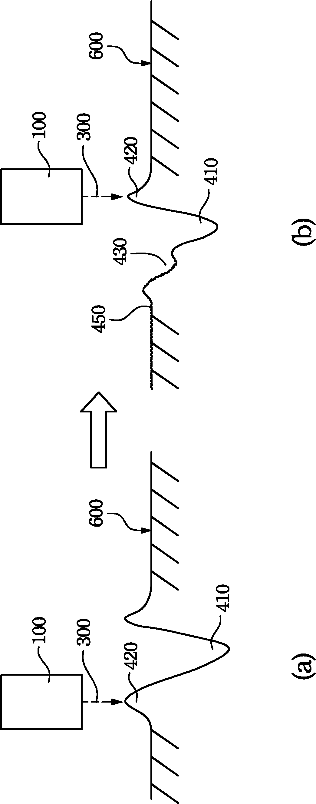
[0028] The invention discloses an embossing mold for completely embossing an optical microstructure pattern so as to maintain the optical rotation performance of a light guide plate.

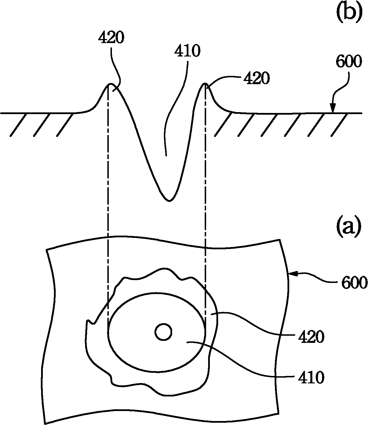
[0029] The invention discloses an embossing mold, which is used to reduce the chance that the protrusions on the periphery of the micro-holes will fall off and fill up the micro-holes.

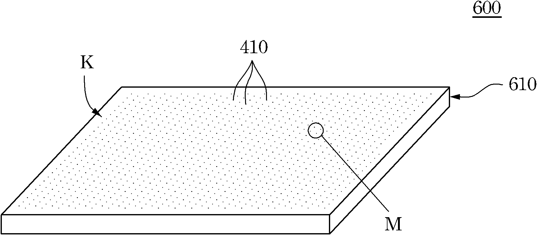
[0030] One embodiment of the present invention discloses an embossing mold. The embossing mold includes a body and a microhole aggregation pattern. The body has a stamping surface. The aggregate pattern of microholes is distributed on the printing surface and includes a plurality of microscopic concave holes. The periphery of each micro-recess has at least one protrusion, and the periphery of each micro-recess and the top surface of the protrusion both have melted surfaces, suc...


PUM


Abstract

The invention relates to a stamping die and a light guide plate thereof. The stamping die comprises a die body and a micropore aggregation pattern, wherein the die body comprises a stamping surface; the micropore aggregation pattern is distributed on the stamping surface and comprises a plurality of micro concave holes, at least one bulge is arranged on the periphery of each micro concave hole, and a molten surface is respectively arranged on the periphery of each micro concave hole and the top surface of the bulge of the micro concave hole. By the invention, the opportunity that the bulges on the peripheries of the micro concave holes fall off to fill the micro concave holes can be reduced, even avoided, thereby further avoiding the problem that a correct optical microstructure pattern can not be stamped on the surface of the light guide plate when the stamping die is used for the optical microstructure pattern on the light guide plate in the following process step; in addition, the service life of a product of the stamping die is also prolonged.

Description

technical field [0001] The invention relates to an embossing mold, in particular to an embossing mold for embossing an optical microstructure pattern on a light guide plate. Background technique [0002] Traditionally, when making optical microstructures on the surface of the light guide plate, one of the methods is to use laser beams to bombard the stamping mold at high temperature, so that the surface of the stamping mold is melted by multiple laser beams to form many micro-holes, so that the stamping mold can be used The micro concave holes on the surface print and emboss corresponding optical microstructures on the surface of the light guide plate. Because the apertures of these concave holes are of micron size, they are called micro concave holes. [0003] However, please refer to Figure 1, which shows a top view (a) and a cross-sectional view (b) of the appearance of a crater with micro-holes in the prior art. [0004] Using a laser beam to bombard the surface of the...

Claims


Application Information

Patent Timeline
Patent Type & Authority Applications(China)
IPC IPC(8): B41K3/00G02B6/00
Inventor 叶钧皓
Owner 苏州向隆塑胶有限公司
Why Eureka
Try Eureka